5. Configure your system
Tabs shown along the top of your VidyoGateway Admin pages for General, Cluster, Services, IVR, Maintenance, and Logout are used to configure different areas of your system. The following sections cover these tabs in more detail.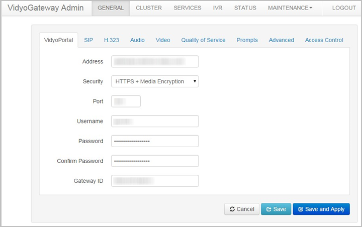
Configure the General settings
The General tab contains subtabs covering settings for VidyoPortal, SIP, H.323, audio, video, Quality of Service, prompts, advanced functions, and access control for your VidyoGateway.
Configure the VidyoPortal settings
The VidyoPortal subtab is used to connect your VidyoGateway to your VidyoPortal.
- You must add your VidyoGateway server as a component on your VidyoPortal. For more information, see "Add a VidyoGateway to your VidyoPortal" in the VidyoPortal and VidyoRouter Administrator Guide.
- The values you provide in the fields on the VidyoPortal subtab are automatically propagated to your Cluster Nodes. Therefore, the VidyoPortal subtab does not appear when accessed from your Cluster Node servers. To make configurations on the tab, you must access it from your Active Controller.
To configure the VidyoPortal settings:
- Log in to the Admin portal using your System Console account. For more information, see VidyoGateway configuration procedure.
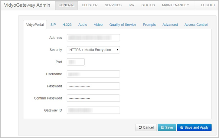
- Enter the IP or FQDN address of the VidyoPortal tenant to which your VidyoGateway will be connected.
- Select None, HTTPS, or HTTPS + Media Encryption from the Security drop-down. For TLS protocol fields to display on the General > SIP tab, you must select HTTPS or HTTPS + Media Encryption. For more information, see Configure SIP settings.
- Enter the port number on which your VidyoGateway listens. Default port numbers for HTTP and HTTPS are 80 and 443, respectively. You can change these values as necessary. The port number in your VidyoGateway must match the value set in your VidyoPortal. You can also configure these ports to match the firewall port range required by H.323/SIP systems as necessary.
- Enter your username in the Username field. This is the username you created when adding your VidyoGateway component on your VidyoPortal. For more information, see Make configurations on your VidyoGateway.
- Enter and confirm your password. This is the password you created when adding your VidyoGateway component on your VidyoPortal.
- Enter the gateway ID for your VidyoGateway in the Gateway ID field. A default value is provided.
- Click Save or Save and Apply as desired.
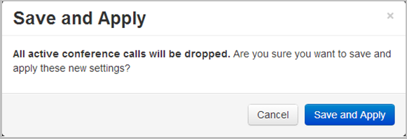
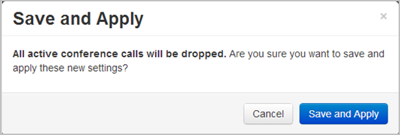
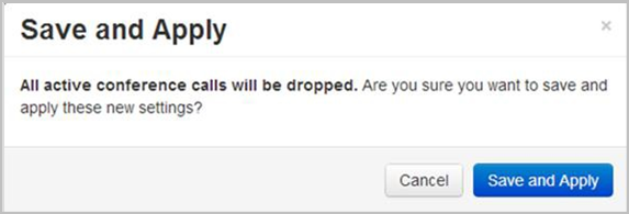
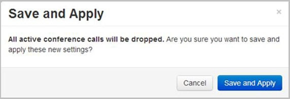
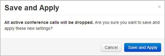
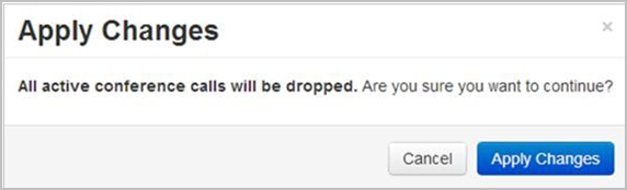
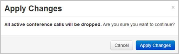
- When you click Save and Apply, a pop-up informs you that the change drops all the active conference calls on your VidyoGateway server.
- Settings made while only clicking Save accrue and are applied when you subsequently click Save and Apply or reboot your VidyoGateway server.
Configure SIP settings
Use the SIP subtab to configure your VidyoGateway session initiation protocol (SIP) settings.
|
Note Values you provide in the fields on the SIP tab are automatically propagated to your Cluster Nodes. Therefore, the SIP tab does not display when accessed from your Cluster Node servers. To make configurations on the tabs, you must access them from your Active Controller. |
To configure the SIP settings:
- Log in to the Admin portal using your System Console account. The General > VidyoPortal page displays by default.
- Click the SIP subtab.
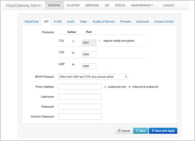
- When using the TLS protocol, provide the following information:
- Select the TLS checkboxes to encrypt the SIP signaling between the VidyoGateway and a proxy server for inbound and outbound calls.
- Enter a port value for TLS.
- Select the require encryption checkbox to only allow calls in which the media is encrypted via the secure real-time transport protocol (SRTP). When this checkbox is not selected, calls without SRTP media encryption are permitted on the VidyoGateway.
- When using the TCP protocol, provide the following information:
- Select the TCP checkboxes to enable SIP over TCP support for inbound and outbound calls.
- When using the UDP protocol, provide the following information:
- Select the UDP checkboxes to enable SIP over UDP for inbound and outbound calls. If both TLS and TCP are not enabled, then all outbound SIP calls will use UDP, which is not encrypted.
- Enter a port value for UDP.
- Use the BFCP Protocol drop-down to select one of the following:
- Select Offer both UDP and TCP to offer and answer both protocols.
- Select Offer only UDP / prefer UDP to only offer the UDP protocol and prefer it when answering calls.
- Select Offer only TCP / prefer TCP to only offer the TCP protocol and prefer it when answering calls.
- When using a proxy address, provide the following information:
- Enter a proxy address in the Proxy Address field.
- Select one of the following:
- Select outbound only if you want to only route outbound calls through your proxy. With outbound only selected, all calls are sent to the proxy; however, inbound calls are accepted from any device.
- Select inbound & outbound of you want to route both inbound and outbound calls through your proxy. With inbound & outbound selected, calls received from any device other than the proxy are rejected.
- Enter the user name for your proxy server in the Username field.
- Enter the password for your proxy server in the Password field.
- Click Save or Save and Apply as desired.
- When you click Save and Apply, a pop-up informs you that the change drops all the active conference calls on your VidyoGateway server.
- Settings made while only clicking Save accrue and are applied when you subsequently click Save and Apply or reboot your VidyoGateway server.
|
Note If you select more than one protocol (for example, TLS, TCP, and/or UDP), inbound traffic will be received on any of the selected protocols. Outbound calls will be routed using the following logic on selected protocols only: Perform an outbound call using the protocol that has a resolved domain record going by the order TLS to TCP to UDP (if selected). If all selected protocols do not have resolved domain records (for example, DNS lookup failed on all selected protocls), the VidyoGateway will attempt an outbound call by the order UDP to TCP to TLS (if selected). For example, if you select all three (TLS, TCP, UDP), the VidyoGateway will be listening to inbound traffic on three protocols. For outbound traffic, the VidyoGateway will attempt TLS first and if the DNS for TLS doesn’t resolve, it will attempt to resolve the DNS for TCP. If that succeeds, the VidyoGateway will make an outbound SIP call using TCP. |
|
Note VidyoGateway can only act as a BFCP server. |
Configure H.323 settings
The H.323 subtab is used to configure your VidyoGateway H.323 protocol settings. However, before you configure your H.323 settings, you must select whether you are using a standalone VidyoGateway (a single component acting as both Controller and VidyoGateway) orclustered VidyoGateways because the fields on the H.323 subtab change depending on which configuration you set.
For more information about standalone and clustered VidyoGateways and about how to set either configuration, see Configure clusters.
|
Note Values you provide in the fields on the H.323 subtab are automatically propagated to your Cluster Nodes. Therefore, the H.323 subtab does not display when accessed from your Cluster Node servers. To make configurations on the tabs, you must access them from your Active Controller. |
Configure H.323 settings when using a Standalone VidyoGateway
When your VidyoGateway is configured as a Standalone VidyoGateway, the following settings are available in the H.323 subtab. For more information, see Configure clusters.
To configure the H.323 settings when using a Standalone VidyoGateway:
- Log in to the Admin portal using your System Console account. The General > VidyoPortal page displays by default.
- Click the H.323 subtab.
- Enter the hostname or IP address of your primary gatekeeper in the Primary Gatekeeper field.
- Enter the name of your alternate gatekeeper in the Alternate Gatekeeper field.
Note
An alternate gatekeeper is automatically registered when the active gatekeeper fails, and it remains connected until the active gatekeeper and the VidyoGateway are restarted.
- Enter your Gatekeeper ID in the Gatekeeper ID field.
- Click Save or Save and Apply as desired.
- When you click Save and Apply, a pop-up informs you that the change drops all the active conference calls on your VidyoGateway server.
- Settings made while only clicking Save accrue and are applied when you subsequently click Save and Apply or reboot your VidyoGateway server.
Configure H.323 settings when clustering your VidyoGateways
When you configure your VidyoGateway as a cluster, the following settings are available in the H.323 subtab. For more information, see Configure clusters.
To configure the H.323 settings when clustering your VidyoGateways:
- Log in to the Admin portal using your System Console account. The General > VidyoPortal page displays by default.
- Click the H.323 subtab. The following screenshot shows the fields that appear when the VidyoGateway has been configured as a cluster VidyoGateway using the Cluster tab described in Configure clusters.
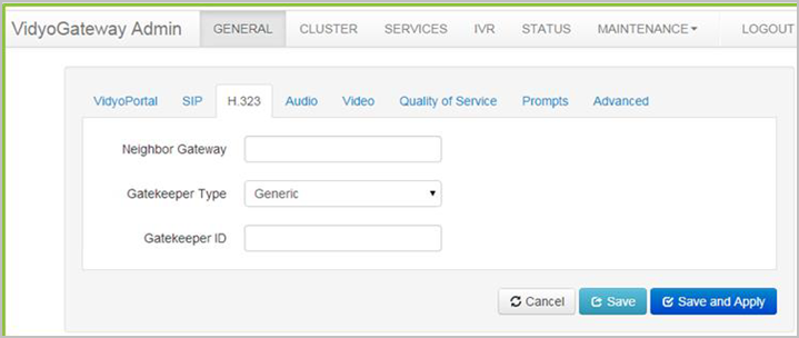
- Enter the hostname or IP address of your gatekeeper in the Neighbor Gateway field.
- Select your gatekeeper type in the Gatekeeper Type drop-down.
- Enter your gatekeeper ID in the Gatekeeper ID field.
Note
Neighboring mode requires reconfiguration of your external H.323 gatekeeper to support neighboring. For more information, refer to your external gatekeeper documentation.
- Click Save or Save and Apply as desired.
- When you click Save and Apply, a pop-up informs you that the change drops all the active conference calls on your VidyoGateway server.

- Settings made while only clicking Save accrue and are applied when you subsequently click Save and Apply or reboot your VidyoGateway server.
- When you click Save and Apply, a pop-up informs you that the change drops all the active conference calls on your VidyoGateway server.
Configure audio settings
To configure the audio settings:
- Log in to the Admin portal using your System Console account. The General > VidyoPortal page displays by default.
- Click the Audio subtab.
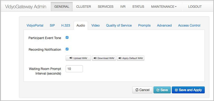
- Select the Participant Event Tone checkbox to sound a tone whenever conference participants join or leave conferences.
- Select the Recording Notification checkbox to play a message or tone whenever the conference is being recorded.
- Select the .wav files as follows:
- Click Upload WAV to select a custom sound file to alert users whenever a recording is happening.
- Click Download WAV to save the sound file being currently used to alert users whenever a recording is happening.
- Click Apply Default WAV to use the original system sound file to alert users whenever a recording is happening.
- Click Save or Save and Apply as desired.
- When you click Save and Apply, a pop-up informs you that the change drops all the active conference calls on your VidyoGateway server.

- Settings made while only clicking Save accrue and are applied when you subsequently click Save and Apply or reboot your VidyoGateway server.
- When you click Save and Apply, a pop-up informs you that the change drops all the active conference calls on your VidyoGateway server.
Configure video loopback settings
Video loopback is not available if IVR is enabled. For more information, see Configure Integrated Voice Response (IVR) sets.
The video loopback image is the on-screen image that the H.323/SIP user sees when connected to a VidyoConnect Room or VidyoRoom and no other participants have entered the video conference. For example, if you call a VidyoConnect Room and no one else has joined the conference yet, instead of seeing an image of yourself in the other tile, you see the loopback image. The image must be a .bmp file.
To configure the video loopback settings:
- Log in to the Admin portal using your System Console account. The General > VidyoPortal page displays by default.
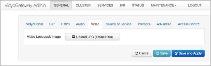
- Click the Video subtab.
- Click Upload BMP (1600X1200) to locate the .bmp image file.
- Click Save or Save and Apply as desired.
- When you click Save and Apply, a pop-up informs you that the change drops all the active conference calls on your VidyoGateway server.

- Settings made while only clicking Save accrue and are applied when you subsequently click Save and Apply or reboot your VidyoGateway server.
- When you click Save and Apply, a pop-up informs you that the change drops all the active conference calls on your VidyoGateway server.
Configure Quality of Service (QoS) settings
The Quality of Service subtab is where you select the service used for prioritizing incoming and outgoing media packets.
You can choose between IP Precedence or Differentiated Services Code Point (DSCP) service types. Depending on the service type selected, you can assign specific values to packets coming from your VidyoGateway to your VidyoRouter and your H.323/SIP device for video, audio, content data, and signaling services set on this screen.
With these specified values assigned to media types coming from your VidyoGateway, you can then configure your network router or switch to prioritize the packets as desired.
|
Tip Look online for the most current IP Precedence or DSCP service value conversion table data. |
Configure QoS settings with IP precedence selected as the Type of Service
To configure quality of service settings with IP precedence selected as the Type of Service:
- Log in to the Admin portal using your System Console account. The General > VidyoPortal page displays by default.
- Click the Quality of Service subtab.
- Select IP Precedence from the Type of Service drop-down.
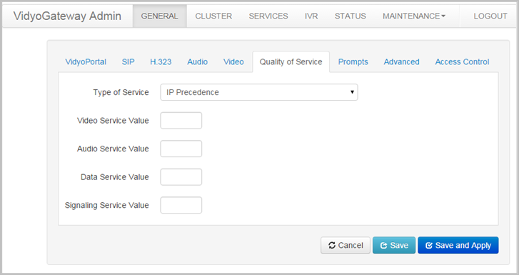
- Enter the appropriate values for your service assignments in the Video Service Value, Audio Service Value, Data Service Value, and Signaling Service Value fields.
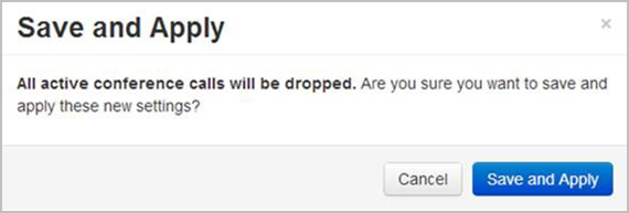
- Click Save or Save and Apply as desired.
- When you click Save and Apply, a pop-up informs you that the change drops all the active conference calls on your VidyoGateway server.
- Settings made while only clicking Save accrue and are applied when you subsequently click Save and Apply or reboot your VidyoGateway server.
- When you click Save and Apply, a pop-up informs you that the change drops all the active conference calls on your VidyoGateway server.
Configure QoS settings with DSCP selected as the type of service
To configure quality of service settings with DSCP selected as the type of service:
- Log in to the Admin portal using your System Console account. The General > VidyoPortal page displays by default.
- Click the Quality of Service subtab.
- Click the Type of Service drop-down and select Differentiated Service Code Point (DSCP).
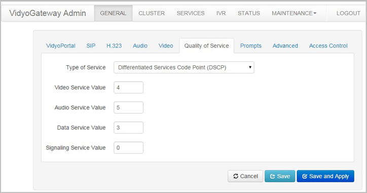
- Enter the appropriate values for your service assignments in the Video Service Value, Audio Service Value, Data Service Value, and Signaling Service Value fields. Leave the default values provided for each of these fields if you are uncertain of the configuration that is needed.
- Click Save or Save and Apply as desired.
- When you click Save and Apply, a pop-up informs you that the change drops all the active conference calls on your VidyoGateway server.
- Settings made while only clicking Save accrue and are applied when you subsequently click Save and Apply or reboot your VidyoGateway server.
- When you click Save and Apply, a pop-up informs you that the change drops all the active conference calls on your VidyoGateway server.
Configure prompts and call control via DTMF tones
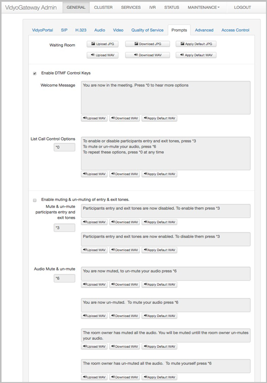
You can use the Prompts subtab to configure the Waiting Room audio messages or videos that call participants hear or see while waiting for a call to begin (for calls where Waiting Room mode is enabled). You can also allow audio-only call participants and video call participants to use DTMF tones to mute or unmute their own audio or video, allow participants to use DTMF tones to mute and unmute entry and exit tones, and more.
This page enables you to upload the BMP/JPG and WAV files that will be played for the participants. All WAV files must be PCM-encoded at 16 KHz sampling.
To configure prompts and call control via DTMF tones:
- Log in to the Admin portal using your System Console account. The General > VidyoPortal page displays by default.
- Click the Prompts subtab.
- In the Waiting Room field, configure any of the following file types to run while the participants are waiting for the call to begin (only for calls where Waiting Room mode is enabled):
- Click Upload BMP/JPG to upload a custom screen image file.
- Click Upload WAV to upload a custom sound file.
- Click Download BMP/JPG to view the screen image file currently in use.
- Click Download WAV to play the sound file currently in use.
- Click Apply Default BMP/JPG to display the default system screen image. A system notification displays indicating that the system has applied the default waiting room BMP.
- Click Apply Default WAV to play the default system sound file. A system notification displays indicating that the system has applied the default waiting room WAV.
Note
The WAV file for the waiting room is played in a loop every 10 seconds after the announcement finishes if the call is in Waiting Room mode. For more information about Waiting Room mode, refer to "Configure room attributes on your tenant" in the VidyoPortal and VidyoRouter Administrator Guide.
- Select the Enable DTMF Control Keys checkbox if you want to allow audio-only call participants to use DTMF tones to mute or unmute their own audio, as well as allow participants to use DTMF tones to mute and unmute the tones that play when they enter or exit a call.
- You can also use the options in this section of the Prompts subtab to change the welcome message and change the list of call control options that audio-only participants will hear when they join a call.
Note
The settings associated with the Enabled DTMF Control Keys (that is, the Welcome Message, List Call Control Options, and Audio Mute and un-mute fields) apply to audio-only participants. Note that the settings for Mute and un-mute participant’s entry and exit tones apply to all participants, not just audio-only participants. For the settings that apply to video participants, see the Enable video control keys setting below.
- In the Welcome Message field, you can change the message that audio-only participants will hear when joining a call by uploading, downloading, or applying a default WAV file:
- Click Upload WAV to select a custom sound file to play.
- Click Download WAV to save the sound file currently being used.
- Click Apply Default WAV to use the default system sound file.
- In the List Call Control Options field, you can change the message about call control options that audio participants will hear by uploading, downloading, or applying a default WAV file:
- Click Upload WAV to select a custom sound file to play.
- Click Download WAV to save the sound file currently being used.
- Click Apply Default WAV to use the default system sound file.
- *0 is the default to list the call control options.
- Select the Enable muting and un-muting of entry and exit tones checkbox if you want to allow users to use DTMF tones to mute and un-mute entry and exit tones.
- In the Mute and un-mute participants entry and exit tones fields, you can change the messages that participants will hear by uploading, downloading, or applying a default WAV file:
- Click Upload WAV to select a custom sound file to play.
- Click Download WAV to save the sound file currently being used.
- Click Apply Default WAV to use the default system sound file.
- *3 is the default to mute and unmute entry and exit tones.
- In the Audio Mute and un-mute fields, you can change the messages that participants will hear by uploading, downloading, or applying a default WAV file:
- Click Upload WAV to select a custom sound file to play.
- Click Download WAV to save the sound file currently being used.
- Click Apply Default WAV to use the default system sound file.
- *6 is the default to mute and unmute the audio.
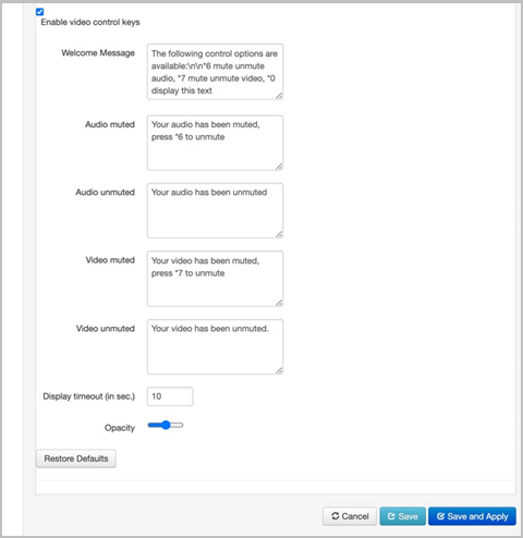
- Select the Enable video control keys checkbox if you want to allow video call participants to use DTMF tones to mute or unmute their own audio and video.
- You can also use the options in this section of the Prompts subtab to change the welcome message, select how long in seconds you want the messages to display, and select how opaque the messages will appear on the screen.
Note
The settings associated with the Enable video control keys (that is, the Welcome Message, Audio muted, Audio unmuted, Video muted, Video unmuted, Display timeout (in sec.), and Opacity fields) apply to video participants. For the settings that apply to audio-only participants, see the Enabled DTMF Control Keys setting above.
- In the Welcome Message field, you can edit the message that video participants will see when joining a call. *0 is the default to display the welcome message.
- In the Audio muted and Audio unmuted fields, you can edit the messages that video participants will see when their audio is muted or unmuted. *6 is the default to mute and unmute the audio.
- In the Video muted and Video unmuted fields, you can edit the message that video participants will see when their video is muted or unmuted. *7 is the default to mute and unmute the video.
- In the Display timeout field, enter the number of seconds the welcome, audio, and video messages will display on the screen.
- Slide the Opacity slider from 0 to 1 to select how opaque the welcome, audio, and video messages will appear over the video. The default is 0.5.
- Click Restore Defaults to restore the settings for the Video Control DTMF on this page to their defaults.
- Click Save or Save and Apply as desired.
- When you click Save and Apply, a pop-up informs you that the change drops all the active conference calls on your VidyoGateway server.
- Settings made while only clicking Save accrue and are applied when you subsequently click Save and Apply or reboot your VidyoGateway server.
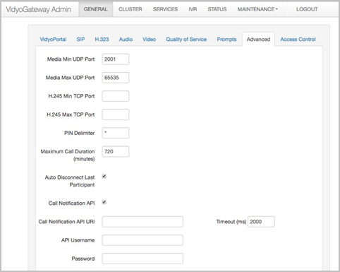
Configure advanced settings
The Advanced subtab is used to configure specific port settings, specify a PIN delimiter, provide the maximum call duration in minutes, and more.
To configure advanced settings:
- Log in to the Admin portal using your System Console account. The General > VidyoPortal page displays by default.
- Click the Advanced subtab.
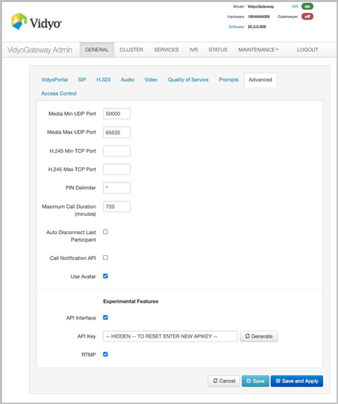
- Enter the UDP ports in the Media Min UDP Port and Media Max UDP Port fields used for media transport between the VidyoGateway and the H.323/SIP device and between the VidyoGateway and the VidyoRouter.
You must specify a minimum range of 1000.
- Enter the lower limit of the port range in the Media Min UDP Port field. The default (and recommended) value is 2001.
- Enter the upper limit of the port range in the Media Max UDP Port field. The default (recommended and maximum) value is 65535.
- Enter the number of TCP ports in the H.245 Min TCP Port and H.245 Max TCP Port fields used for media transport between the VidyoGateway and the H.323/SIP device and between the VidyoGateway and the VidyoRouter.
You must specify a minimum range of 1000.
- Enter the minimum port number in the H.245 Min TCP Port field to use for H.243 traffic. The value must be an inclusive number between 1 and 65535.
- Enter the maximum port number in the H.245 Max TCP Port field to use for H.243 traffic. The value must be an inclusive number between 1 and 65535.
- Enter the character you want used as the separator between the username and the personal identification number on PIN-protected endpoint call requests in the PIN Delimiter field.
- Enter a value in the Maximum Call Duration (minutes) field. This option specifies the maximum length of a VidyoGateway call. This value defaults to 720 minutes (12 hours) and can be increased or decreased as needed.
- Select the Auto Disconnect Last Participant checkbox to configure the system to automatically disconnect from a conference if there is only one VidyoGateway participant left in the conference. If this option is unchecked, the participant will be automatically disconnected once the Maximum Call Duration timer is expired.
- Select the Call Notification API checkbox if you want to enable VidyoGateway to convey to the external application the details of an incoming call (including the extension dialed, source IP address, protocol, and device information) and to receive a response with either a new dial string that will be used for connecting the call to the VidyoPortal or an indication to reject the incoming call.
 When you select this checkbox, additional fields appear, and you must do the following:
- Enter the URI address in the Call Notification API URI field for which the API call should be made.
- Enter the time in milliseconds in the Timeout (in ms) field, to wait to get a response back from the external application. The default is 2000 ms.
- Enter the credentials in the optional API Username and Password fields to be used for authentication against the external application.
- 425 is mapped to “Retry Locked Room”
- 404 is mapped to “Retry Conference Extension”
- Other faults are mapped to “Retry Room Generic Error”
- Select the Use Avatar checkbox if you want an avatar of the first three letters of an audio-only participant’s name to appear on their tile when their video source is muted (that is, when that participant is in audio-only mode). Leave the checkbox unselected if you do not want a participant’s video tile to display at all when their video source is muted.
- In the Experimental Features section of the Advanced page, you can select the API Interface checkbox if you want to allow API requests to go through to the VidyoGateway (but only after you’ve authenticated using the API key as described in the following step). Removing the checkmark prevents any API requests from going through to the VidyoGateway.
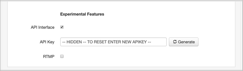
- If you selected the API Interface checkbox, click Generate to obtain an API key.
- After you obtain the key, pass it in an API request to the VidyoGateway. Once you’ve authenticated via the key in this way, you can then pass other API commands to the VidyoGateway.
- Starting with VidyoGateway version 20.2.0, you can send the API requests via https. Prior to version 20.2.0, only http was supported.
- Regenerating a new key invalidates any previously generated keys.
- Select the RTMP checkbox if you want to enable RTMP streaming.
- VidyoGateway version 20.2.0 and later supports RTMPS, a secure form of RTMP (Real Time-Messaging Protocol). RTMPS works on a TSL/SSL connection, which encrypts your live streaming video with an extra layer of security to prevent a third party from intercepting your data.
- To use RTMPS when establishing a stream via the VidyoGateway, simply enter “rtmps” in the stream destination.
- For more information, refer to VidyoGateway experimental features for on-premise.
- Click Save or Save and Apply as desired.
- When you click Save and Apply, a pop-up informs you that the change drops all the active conference calls on your VidyoGateway server.
- Settings made while only clicking Save accrue and are applied when you subsequently click Save and Apply or reboot your VidyoGateway server.
- When you click Save and Apply, a pop-up informs you that the change drops all the active conference calls on your VidyoGateway server.
|
Note The faults received from the external application are mapped to the following IVR prompts: |
|
Caution Once you have enabled the Call Notification API, Vidyo strongly recommends that you check the connectivity to the external application. Since all incoming calls will then be routed via the external application, you must ensure that you have not inadvertently configured the external application to prevent calls from being sent to the VidyoPortal. |
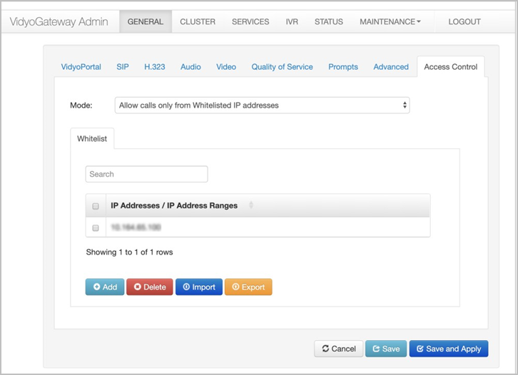
Configure access control settings
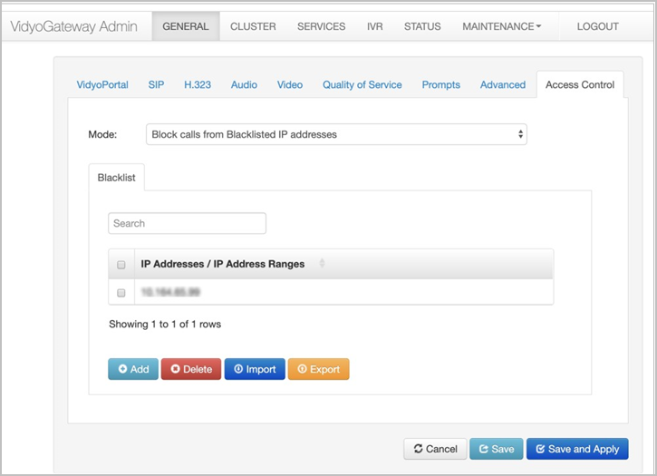
The Access Control subtab is used for protecting the VidyoGateway from intrusion or DoS attacks. The administrator can configure the VidyoGateway for one of three modes.
To configure access control settings:
- Log in to the Admin portal using your System Console account. The General > VidyoPortal page displays by default.
- Click the Access Control subtab.
- Select the appropriate option from the Mode drop-down.
- Allow all calls will not block any calls from reaching the VidyoGateway.
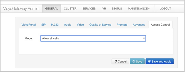
- Allow calls only from whitelisted IP addresses will only allow incoming calls from pre- configured IP addresses.
- Enter IPs that have been configured to interact with the VidyoGateway in the Search field. The search results display below.
- Click Add to add additional IPs and IP ranges.
- Select the checkbox to the left of the IP Address or IP Address Range that needs to be deleted and click Delete.
- Click Import to import a .csv file that contains a list of IPs and IP ranges.
- Click Export to export the IPs and IP ranges.
- Block calls from blacklisted IP addresses will allow incoming calls that are not configured in the blacklist table.
- Enter IPs that have been configured to be blocked from reaching the VidyoGateway in the Search field. The search results display below.
- Click Add to add additional IPs and IP ranges.
- Select the checkbox to the left of the IP Address or IP Address Range that needs to be deleted and click Delete.
- Click Import to import a .csv file that contains a list of IPs and IP ranges.
- Click Export to export the IPs and IP ranges.
- Allow all calls will not block any calls from reaching the VidyoGateway.
- Click Save or Save and Apply as desired.
- When you click Save and Apply, a pop-up informs you that the change drops all the active conference calls on your VidyoGateway server.

- Settings made while only clicking Save accrue and are applied when you subsequently click Save and Apply or reboot your VidyoGateway server.
- When you click Save and Apply, a pop-up informs you that the change drops all the active conference calls on your VidyoGateway server.
VidyoGateway clusters
The following section contains the information required to configure VidyoGateway clusters.
Configure clusters
A VidyoGateway can be configured as a single Standalone VidyoGateway (a single component acting as both Controller and VidyoGateway) or as a cluster setup with an Active Controller, Standby Controller, and Cluster Node VidyoGateway.
This section explains various VidyoGateway cluster configurations used to support as many H.323 and SIP calls required prior to going through the Cluster tab in the VidyoGateway Admin Pages. Think of a VidyoGateway cluster as a large, single VidyoGateway system.
|
Note With clustering enabled on your VidyoGateway, some security scanners may indicate the presence of Telnet as running on your server. This detection is a false positive and Telnet is not actually running on your VidyoGateway. When configuring your VidyoGateways as a cluster, you must export the pre-shared key from your Active Controller and import it into your Standby Controller and Cluster Nodes. Otherwise, calls on your Standby Controller or Cluster Nodes will not be visible from the STATUS tab in your Active Controller. |
Clustering benefits
VidyoGateway clustering enables you to scale your VidyoGateway capacity to hundreds of simultaneous calls by deploying multiple VidyoGateways per VidyoPortal and per tenant. By clustering, you are enabling the multiple VidyoGateways to balance both the H.323 and SIP load, thereby increasing your call scalability.
When creating clusters, you need to assign Controller 1 to one of your VidyoGateways and designate the other VidyoGateways as Controller 2 and/or Cluster Node. Any VidyoGateway can be a Controller 1, Controller 2, or Cluster Node in your VidyoGateway cluster. The Active and Standby Controller roles will be automatically assigned by the system to two controllers (Controller 1 and Controller 2).
The Active Controller automatically sends calls to the first available VidyoGateway in your cluster.
To assign the VidyoGateway Standalone, Controller 1, Controller 2, or Cluster Node, use the Cluster tab.
Note The Active Controller automatically sends calls to the first available VidyoGateway in your cluster. |
Cluster configuration with a H.323/SIP gatekeeper interface
After configuring your VidyoGateway cluster, you can then configure your system to interface with a H.323/SIP gatekeeper as shown in the following illustration.
For more information about configuring gatekeepers, see Configure H.323 Settings.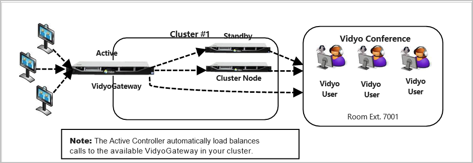
Deploy multiple VidyoGateway clusters
If you deploy large-scale, geographically diverse networks serving multiple tenants, you can provision multiple VidyoGateway clusters in a single VidyoPortal. In such cases, you may want to dedicate scalable VidyoGateway clusters to certain locations or tenants as shown in the following illustration.
The VidyoGateway setting for pointing to a specific VidyoPortal is done from the General > VidyoPortal tab. For more information, see Configure the VidyoPortal settings.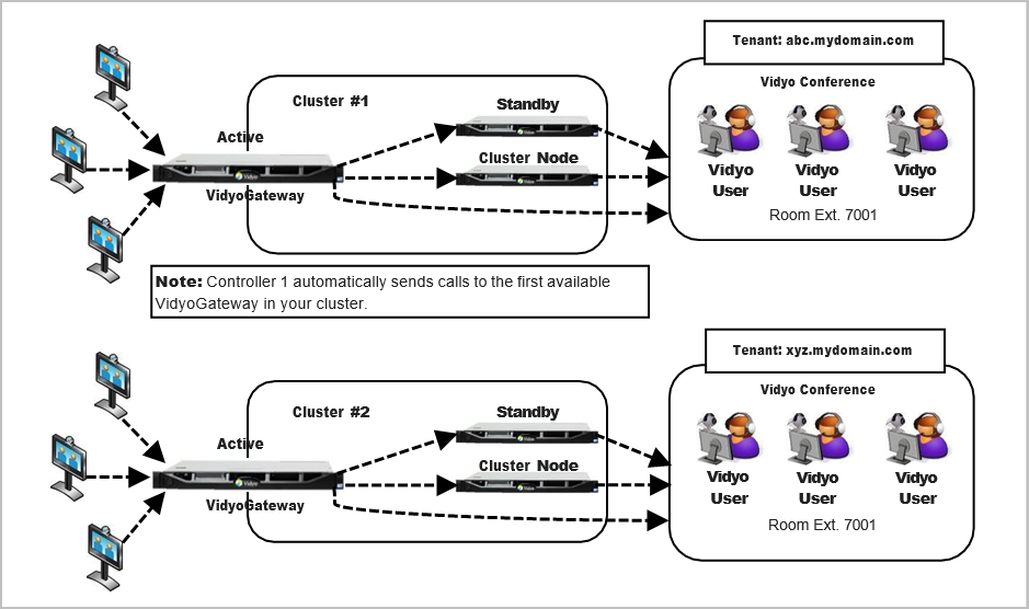
The Standby Controller and Cluster Nodes must be associated with their corresponding Active Controller. This is done by entering the specific Controller 1 Peer IP Address in to the Shared Controller IP Address field for the Controller 2 and Cluster Node VidyoGateways on the Cluster tab.
About clustering
The CLUSTER tab provides options to configure your VidyoGateway server as a Standalone, Controller 1, Controller 2, or Cluster Node. The following sections cover these configurations in more detail.
Each VidyoGateway server in your cluster must align to the following requirements:
- A public IP addresses must be used. This means none of the VidyoGateway servers in your cluster can be NATed.
- If they are behind a firewall, it must permit H.323/SIP ports for each VidyoGateway server in your cluster. This is usually configured as a set range of IP addresses in your firewall.
- Each VidyoGateway server in your cluster must have IVR Enabled and identical IVR configurations. For more information, see Configure Integrated Voice Response (IVR) sets.
- Each VidyoGateway server in your cluster must all be physically located in the same data center. The clustering functionality does not support VidyoGateways located in separate data centers.
- Each VidyoGateway server in your cluster must have a properly configured hostname, IP address, and shared IP address. The information for each of these fields is required for the cluster to work. The shared IP address is the one that will be dialed by incoming calls. For more information, see Configure Controller 1, Configure Controller 2 and Configure your cluster node.
- VidyoGateway high availability relies on the address resolution protocol (ARP) request to determine whether the floating IP address is up. If it is not up, the VidyoGateway (active or standby) takes possession of the shared IP address.
The Cluster Configuration screen allows you to specifically designate your machine as a Standalone, Controller 1, Controller 2, or Cluster Node VidyoGateway. You can also provide additional data for each component depending on the machine’s VidyoGateway cluster role. A specific email address can be set on the Controller nodes to send an automatic failover notification for protective measures.
When the Active Controller is configured properly, the following takes place in the event of a failure:
- Existing calls fail as the Standby Controller takes the IP address of the Active Controller that went down.
- The new Active Controller sends out the email notification alerting users of the system failure.
Note
The original Active Controller must be repaired with its original hardware and software intact to be returned to your system setup.
Clustering procedure overview
The following steps provide an overview of how to configure your VidyoGateway cluster:
- Make sure you’ve assigned a hostname to Controller 1, and then reboot your machine. For more information, see View application and system information.
- Access Controller 2 and assign a different hostname to it, and then reboot your machine. For more information, see View application and system information.
- Configure the cluster settings on Controller 1, reboot, and then reboot your machine. For more information, see Configure Controller 1.
- Configure the nodes for the active controller. For more information, see Configure nodes for the active controller in cluster mode.
- Configure the cluster settings on Controller 2, reboot, and then reboot your machine. For more information, see Configure Controller 2.
- Configure the cluster settings on your Cluster Node, and then reboot your machine. For more information, see Configure your cluster node.
The original Active Controller should be returned to your system setup and configured as a Standby Controller.
We recommend you replace the original Controller 1 with a Cluster Node (if you have one in your system setup). The Cluster Node VidyoGateway is then recognized as a Standby Controller, but is mislabeled as the Cluster Node.
|
Note If desired, you can reconfigure your Controllers to bear the correct Controller 1 and Controller 2 labeling. However, this is not required and the system is fully functional in this state. |
Some people set up VidyoGateway systems with a single Standalone VidyoGateway (a single component acting as both Controller and VidyoGateway). Other clients designate Controller 1, Controller 2, and Cluster Node VidyoGateways. You can think of the latter as a large, single VidyoGateway system.
A variety of VidyoGateway cluster configurations are used to support H.323 and SIP call volume requirements.
The following sections show you how to configure each VidyoGateway component type using the CLUSTER tab.
Configure your Standalone VidyoGateway
Your server is set as a Standalone VidyoGateway by default. Unless it’s changed, you don’t need to modify the configuration.
|
Note The SERVICES tab and the Clusters > Nodes subtab will not display once the Standalone VidyoGateway is configured. |
To configure your Standalone VidyoGateway:
- Log in to the Admin portal using your System Console account. The General > VidyoPortal page displays by default.
- Click the CLUSTER tab.
- Select Standalone from the Mode drop-down.
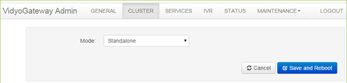
- Click Save and Reboot.
- Any modifications you make to your clusters accrue until you click Save and Reboot, and then all your cluster changes are applied to your VidyoGateway server.
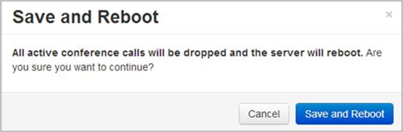
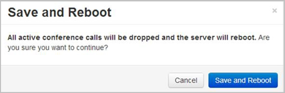
- When you click Save and Reboot, a pop-up informs you that the change drops all the active conference calls on your VidyoGateway server.

- Any modifications you make to your clusters accrue until you click Save and Reboot, and then all your cluster changes are applied to your VidyoGateway server.
Configure Controller 1
Before configuring clusters, be sure to review the Clustering procedure overview.
To configure Controller 1:
- Log in to the Admin portal using your System Console account. The General > VidyoPortal page displays by default.
- Click the CLUSTER tab.
- Select clustered from the Mode drop-down.
- Select Controller 1 from the Role drop-down.
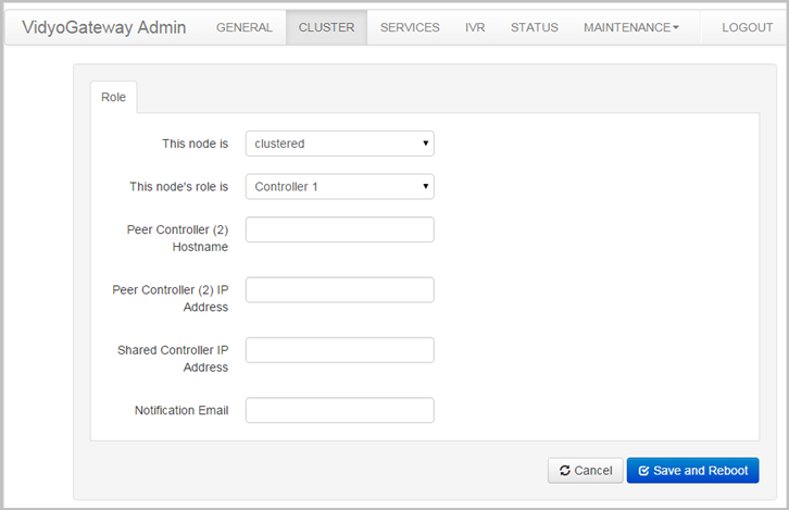
- Configure Controller 1 as follows:
- Enter a Controller 2 hostname in the Peer Controller (2) Hostname field. Provide the hostname exactly as it’s shown in the System Console and do not provide an FQDN as the Peer Host Name. For more information, see View application and system information.
- Enter a Controller 2 IP address in the Peer Controller (2) IP Address field.
- Enter a Shared Controller IP address in the Shared Controller IP Address field. This is the address that will be dialed by incoming calls (including H.323/SIP callers).
- Enter a notification email address in the Notification Email field. This is the email address where you want to receive notifications in the event of a system failure.
- Click Save and Reboot.
- Any modifications you make to your Clusters accrue until you click Save and Reboot, and then all your Cluster changes are applied to your VidyoGateway server.
- When you click Save and Reboot, a pop-up informs you that the change drops all the active conference calls on your VidyoGateway server.
- Any modifications you make to your Clusters accrue until you click Save and Reboot, and then all your Cluster changes are applied to your VidyoGateway server.
Configure nodes for the active controller in cluster mode
You must manually add any nodes other than the Active Controller since it will automatically be added to the Nodes page after reboot.
|
Note The Nodes subtab is only visible when accessing the VidyoGateway Admin Pages for the Active Contoller. |
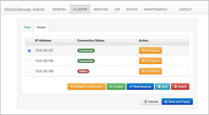
The node may display as follows depending on its current connection status:
| Connection Status | Color | Description |
| Maintenance / Off | Gray | Node is in maintenance mode and not registered with the controller |
| Maintenance | Blue | Node is in maintenance mode and still registered to the controller |
| Offline | Red | Node is not registered with the controller and not in maintenance mode |
| Connected | Green |
Node is accepting calls |

To configure nodes for the active controller in cluster mode:
- Log in to the Admin portal using your System Console account. The General > VidyoPortal page displays by default.
- Click the CLUSTER tab. The Cluster > Role page displays by default.
- Click the Nodes subtab.

- Click Add. The Add A Media Node pop-up displays.
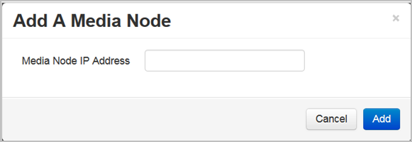
- Enter the media note IP address in the Media Node IP Address field.
- Click Add. The new media node IP address is added to the Nodes page with a connection status of “NEW.”
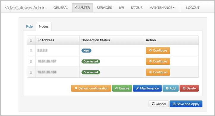
- Click Save and Apply.
- Any modifications you make to this page accrue until you click Save and Apply, and then all your changes are applied to your VidyoGateway server.
- When you click Save and Apply, a pop-up informs you that the change drops all the active conference calls on your VidyoGateway server.
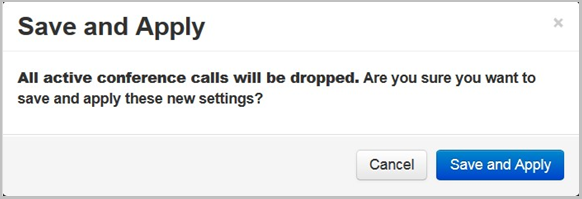
- Any modifications you make to this page accrue until you click Save and Apply, and then all your changes are applied to your VidyoGateway server.
|
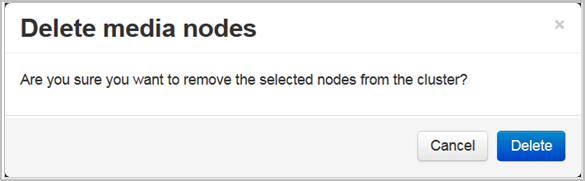
Note To delete the media node IP Address, select the checkbox to the left of the IP Address column and click Delete. A Confirmation pop-up displays. |
View and Edit the Default Node Configuration
The default node configuration applies to all the nodes unless a node has an individual configuration. Likewise, any edits that you make to the default node configuration apply to all the nodes unless a node has an individual configuration. For information about configuring an individual node, see Perform an individual node configuration.
To view and edit the default node configuration:
- Log in to the Admin portal using your System Console account. The General > VidyoPortal page displays by default.
- Click the CLUSTER tab. The Cluster > Role page displays by default.
- Click the Nodes subtab.
- Click Default configuration.
The Configure pop-up displays showing the current default configuration.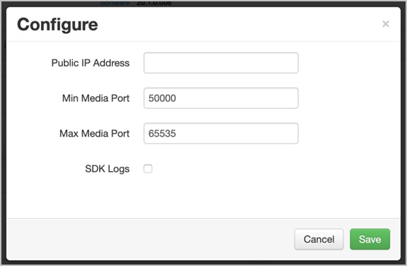
- Enter the public IP address in the Public IP Address field.
The Public IP Address field is blank only when you first access this screen. Once you enter the default public IP address, it will automatically appear in this field from then on, and it will be applied to all the nodes unless a node has an individual configuration. For more information about the public IP address, see Configure a public IP address and enable Static NAT mode. - Change the default minimum media port in the Min Media Port field if desired.
- Change the default maximum media port in the Max Media Port field if desired.
- Select the SDK Logs checkbox if you would like to generate SDK logs. Selecting this checkbox results in larger logs; therefore, this checkbox is typically selected only for troubleshooting purposes.
- Click Save. This configuration is then applied to all the nodes unless a node has its own individual configuration as described in the following section.
Perform an individual node configuration
If you don’t want a particular node to have the same configuration as the default node, you can perform an individual node configuration.
To perform an individual node configuration:
- Log in to the Admin portal using your System Console account. The General > VidyoPortal page displays by default.
- Click the CLUSTER tab. The Cluster > Role page displays by default.
- Click the Nodes subtab.
- Click CONFIGURE next to the node you want to modify.

The Configure pop-up displays.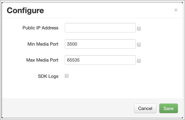
- Do one of the following in the Public IP Address field:
- If you want to use a public IP address other than the default one, enter a public IP address. For more information about the public IP address, see Configure a public IP address and enable Static NAT mode.
- If you want to use the default public IP address, select the checkbox. When you select the checkbox, the text box near it becomes disabled.
- Do one of the following in the Min Media Port and Max Media Port fields:
- If you want to use a minimum media port or maximum media port other than the default ones, enter the port numbers in the respective fields.
- If you want to use the default minimum media port or maximum media port, select the checkbox next to the respective field(s). When you select a checkbox, the text box near it becomes disabled.
- Select the SDK Logs checkbox if you would like to generate SDK logs for this individual node.
- Click Save. This configuration is then applied to the individual node you selected. Any changes you subsequently make to the default node configuration will be applied only to the fields that have the checkboxes selected (that is, the default configuration will not to be applied to the fields where you entered an individual configuration).
Place VidyoGateway cluster nodes in Maintenance mode
When VidyoGateway cluster nodes are placed in Maintenance mode, existing calls remain connected but new calls are not received. Only VidyoGateway cluster nodes that are online can be placed in Maintenance mode.
|
Note When a node that has a status connection of offline, maintenance, or maintenance/off is selected and the Maintenance button is clicked, an error message displays stating “Only Online nodes may be put into Maintenance node”. |
To place VidyoGateway cluster nodes in maintenance mode:
- Log in to the Admin portal using your System Console account. The General > VidyoPortal page displays by default.
- Click the CLUSTER tab. The Cluster > Role page displays by default.
- Click the Nodes subtab.
- Select the checkbox for the appropriate node.
- Click Maintenance.

The Start Maintenance pop-up displays.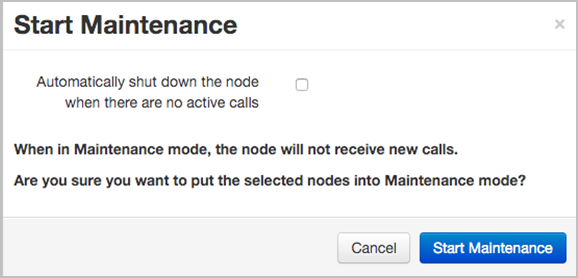
- Select the Automatically shutdown the node when there are no active calls checkbox if necessary.
Note
Only Virtual Edition appliances will be automatically shut down. Physical appliances will ignore this command.
- Click Start Maintenance. The node’s connection status changes to “Maintenance.”
Enable VidyoGateway cluster nodes
Only VidyoGateway clusters that are in Maintenance mode can be enabled.
|
Note When a node that has a connection status of offline, online, or maintenance/off is selected and the Enable button is clicked, an error message displays stating “Only nodes in Maintenance mode may be Enabled.” |
To enable VidyoGateway cluster nodes:
- Log in to the Admin portal using your System Console account. The General > VidyoPortal page displays by default.
- Click the CLUSTER tab. The Cluster > Role page displays by default.
- Click the Nodes subtab.
- Select the checkbox for the appropriate node.
- Click Enable. The Enable Node pop-up displays.
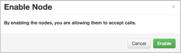
- Click Enable. The node’s connection status changes back to “Connected.”
Configure Controller 2
- Before configuring clusters, be sure to review the Clustering procedure overview.
- When using VidyoGateway version 3.2 and later, your Services automatically propagate from your Active Controller to the Standby Controller and Cluster Nodes. Therefore, the Services tab does not display when accessed from your Standby Controller. To make configurations on the tabs, you must access them from your Active Controller. In addition, the fields on the General > VidyoPortal, SIP, and H.323 subtabs are automatically populated from Controller 1. Please note that these fields will be grayed out since they are not configurable on the Standby Controller.
- If you choose to enable IVR on your Active Controller, you must also enable it on your Standby Controller and all the Cluster Nodes.
To configure Controller 2:
- Log in to the Admin portal using your System Console account. The General > VidyoPortal page displays by default.
- Click the CLUSTER tab.
- Select clustered from the Mode drop-down.
- Select Controller 2 from the Role drop-down.
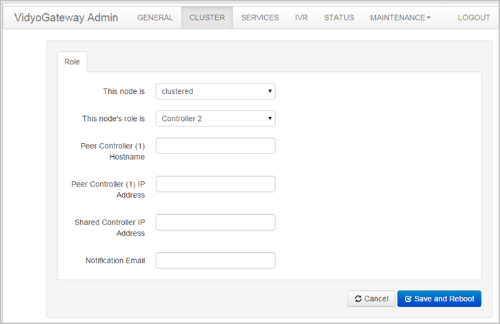
- Configure Controller 2 as follows:
- Enter a Controller 1 hostname in the Peer Controller (1) Hostname field. Provide the hostname exactly as it’s shown in System Console Option 1. Do not provide an FQDN as the Peer Host Name. For information, see View application and system information.
- Enter a Controller 1 IP address in the Peer Controller (1) IP Address field.
- Enter a shared controller IP address in the Shared Controller IP Address field. This is the address H.323/SIP callers will use.
- Enter a notification email address in the Notification Email field. Enter the email address you want to receive notifications in the event of a system failure.
Before clicking Save and Reboot, please ensure that Controller 1 is reachable from Controller 2.
- Click Save and Reboot.
- Any modifications you make to your Clusters accrue until you click Save and Reboot, and then all your Cluster changes are applied to your VidyoGateway server.
- When you click Save and Reboot, a pop-up informs you that the change drops all the active conference calls on your VidyoGateway server.

Configure your cluster node
- Before configuring clusters, be sure to review the Clustering procedure overview.
- When using VidyoGateway version 3.2 and later, your services and VidyoPortal, SIP, H.323 configurations automatically propagate from your Active Controller to the Cluster Nodes. Therefore, the Services tab as well as the VidyoPortal, SIP, H.323 tabs (under General) do not display when accessed from your Cluster Node servers. To make configurations on the tabs, you must access them from your Active Controller.
- If you choose to enable IVR on your Active Controller, you must also enable it on your Standby Controller and all the Cluster Nodes.
To configure your cluster node:
- Log in to the Admin portal using your System Console account. The General > VidyoPortal page displays by default.
- Click the CLUSTER tab.
- Select clustered from the Mode drop-down.
- Select Cluster Node from the Role drop-down.
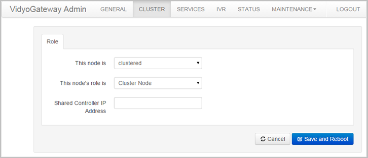
- Enter a shared controller IP address in the Shared Controller IP Address field.
- Click Save and Reboot.
- Any modifications you make to your Clusters accrue until you click Save and Reboot, and then all your Cluster changes are applied to your VidyoGateway server.
- When you click Save and Reboot, a pop-up informs you that the change drops all the active conference calls on your VidyoGateway server.
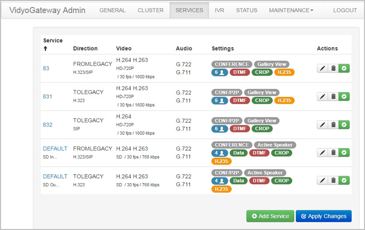
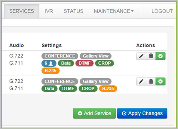
Manage services
The SERVICES tab allows you to manage and configure prefixes for various call types both from and to H.323/SIP devices.
|
Note At least one service with From Legacy as the Direction must be set as the default to use IVR. For more information about the Default service setting, see Add a service. |
VidyoGateway services specify the type of call, the direction (to and from), and specific profile details. Prefixes are used when creating a dialing plan (if required) or when isolating a call through a specific VidyoGateway is necessary.
The VidyoGateway comes with preconfigured services for a variety of protocols. These defaults allow you to dial without specifying any prepending digits when sending or receiving calls from H.323/SIP devices. You can modify these services or add new ones. For some service examples, see VidyoGateway VM provisioning requirements.
- When clustering your VidyoGateways, your Services are centralized; meaning, the ones configured on your Active controller are used on all servers in your cluster. For more information about Clustering, see Configure clusters.
- For information about specific call types and services, see Call types and service examples.
Add a service
When adding or editing a service for audio-only calls, the administrator can choose an audio codec to be used during calls. However, when adding or editing a service for video calls, the audio codec is negotiated as part of the call setup.
To add a service:
- Log in to the Admin portal using your System Console account. The General > VidyoPortal page displays by default.
- Click the SERVICES tab.
- Click Add Service. The Add Service pop-up displays.
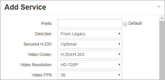
- Enter configuration settings for your new service. Available choices include the following:
- Enter a numeric prefix for your configuration in the Prefix field.
- Select the Default checkbox to not require a dialing prefix when a user dials from a H.323/SIP (a.k.a. Legacy) endpoint.
At least one service with From Legacy as the direction must be set as the default to use IVR. For more information, see Enable your IVR settings. - Select a call direction from the Direction drop-down for your prefix configuration as either From or To Legacy.
- If you select To Legacy from the Direction drop-down, the Call Type field becomes read-only with Conference/P2P selected.
- If you select From Legacy from the Direction drop-down, you must select either Conference or P2P from the Call Type drop-down.
- If you select To Legacy from the Direction drop-down, the Call Type field becomes read-only with Conference/P2P selected.
- Select one of the following security options from the Secured H.235 drop-down:
- Select No to not have your H.235 transmissions secured.
- Select Optional to have H.235 calls secured between your VidyoGateway and H.323/SIP devices that support encryption for the protocol.
- Select Required to have H.235 calls secured between VidyoGateway and H.323/SIP devices at all times (regardless of H.323/SIP endpoint support for encryption for the protocol).
- If H.323/SIP endpoint calls are set to Required, your VidyoPortal must be running the Vidyo encryption software option for a successful connection.
- Select Voice Only, H.264, H.263, H.264/H.263, or H263/H.264 as your video codec from the Video Codec drop-down. When you select Voice Only, the Bandwidth field becomes read-only and the Resolution and FPS drop-downs disappear from the Add Service pop-up.
- Select CIF, SD, HD-720P, or FHD-1080P as your resolution from the Video Resolution drop-down.
The setting determines the maximum resolution used for your service.
- When you select a Resolution value, the Bandwidth is changed accordingly in the following manner: CIF = 384 kbps, SD = 768 kbps, HD-720P = 1600 kbps, and FHD-1080P = 3072 kbps.
- If you select the Voice Only option as your Video Codec, the Resolution is fixed at 64 kbps.
- Although you must select a Resolution when you configure your service, the system dynamically negotiates both the bandwidth and resolution according to the H.323/SIP device. VidyoGateway does not negotiate higher than the configured resolution.
- Select 5, 10, 15, 20, 25, or 30 from the Video FPS drop-down as your frames per second.
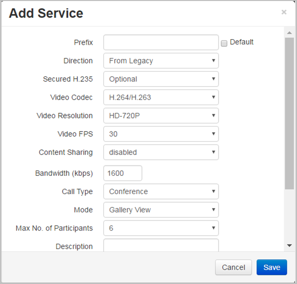
- Select one of the following options from the Content Sharing drop-down:
- Select disabled to disable support for the BFCP and H.239 protocols, as well as content sharing between H.323 and SIP devices.
- Select enabled to enable support for the BFCP and H.239 protocols, as well as content sharing between H.323 and SIP devices.
The enabled option enables support for the BFCP and H.239 protocols. This allows content sharing between H.323 and SIP devices, along with the ability to configure bandwidth allocation between the main video and content share.
The following drop-downs display in the Add Service pop-up upon selecting the enabled option from the Content Sharing drop-down: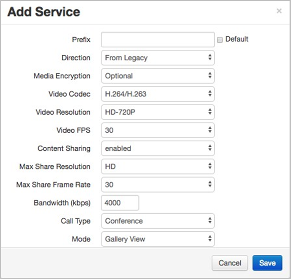
- Select 1080HD, HD, SD, or CIF from the Max Share Resolution drop-down as the max content share resolution.
- Select 30, 25, 20, 15, or 10 from the Max Share Frame Rate drop-down as the max content share frame rate.
- Enter a numeric value (in kbps) in the Bandwidth (kbps) field for the maximum bandwidth available for your service.
- The number that displays in this field is based on the Resolution selected in the following manner: 384 kbps = CIF, 768 kbps = SD, 1600 kbps = HD-720P, and 3072 kbps = FHD 1080P.
- If you select the Voice Only option as your Video Codec, the Resolution is fixed at 64 kbps.
- Select P2P (Point to Point, from Legacy only) or Conference (to Legacy) from the Call Type drop-down as your audio codec. This field only displays when From Legacy is selected in the Direction field. If To Legacy is selected as the direction, the field is fixed as Conference/P2P.
- Select from the following from the Mode drop-down:
- Select Gallery View to display participants in a filmstrip-type layout.
- Select Active Speaker to display the most recent speaker in a larger window than other users.
- Select Continuous Presence to display all participants in equal-sized windows.
- Select 1, 2, 3, 4, 5, 6, 7, or 8 from the Max No. of Participants drop-down as your specified maximum number of participants to be shown.
- Enter a service name in the Description field for your configuration.
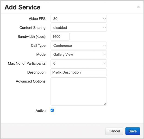
- In the Advanced Options field, you can configure various options. For more information, see the following section, Configure Advanced Options.
- Select the Active checkbox to make your service and all its settings available for use on your system.
- Do not select the checkbox if you do not want to make your service and all its settings available for use on your system.
- You can also click the corresponding checkbox to the right of the list of services to activate and deactivate services from the Service tab.
- Click Save in the Add Service pop-up. If desired, you can also select the Edit, Delete, Activate, or Deactivate buttons on the Services tab.
- Click Apply Changes on the Services page if desired.
- Any services you edit, delete, activate, and deactivate accrue until you click Apply Changes, and then all your Service changes are applied to your VidyoGateway server.
- When clicked, a pop-up informs you that the change drops all the active conference calls on your VidyoGateway server.
Configure Advanced Options
In the Advanced Options field of the Add Service pop-up, you can configure various advanced options, such as the fromURI parameter and display name masking.
Configure the fromURI parameter
The fromURI parameter allows administrators to enter a parameter that all outbound calls must use if they are dialed via the indicated profile.
This option is available starting with VidyoGateway version 22.2.0.
To configure the fromURI parameter:
- Log in to the Admin portal using your System Console account. The General > VidyoPortal page displays by default.
- Click the SERVICES tab.
- Click Add Service. The Add Service pop-up displays.
- In the Advanced Options field, add the fromURI: parameter. Any outbound calls dialed via that profile will then use that parameter.
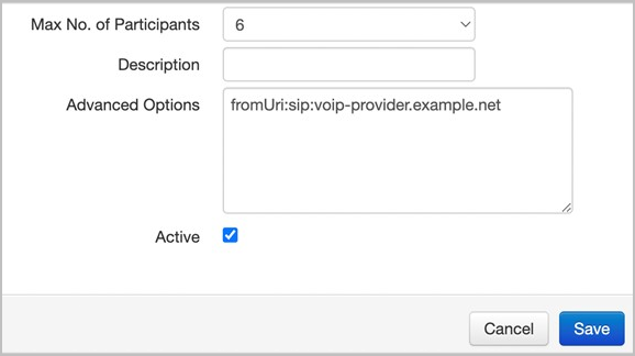
- Click Save to save the fromURI parameter.
Configure display name masking
To enhance privacy and security, administrators can mask the VidyoGateway dial-in or dial-out display name. The dnMask Advanced Option masks the caller’s phone number so others cannot view it.
This option is available starting with VidyoGateway version 24.2.0.
To configure display name masking:
- Log in to the Admin portal using your System Console account. The General > VidyoPortal page displays by default.
- Click the SERVICES tab.
- Click Add Service. The Add Service pop-up displays.
- In the Advanced Options field, add dnMask: and the prefix that indicates the number of digits to mask. In the following example, 8-* masks the last eight digits of the caller’s phone number.
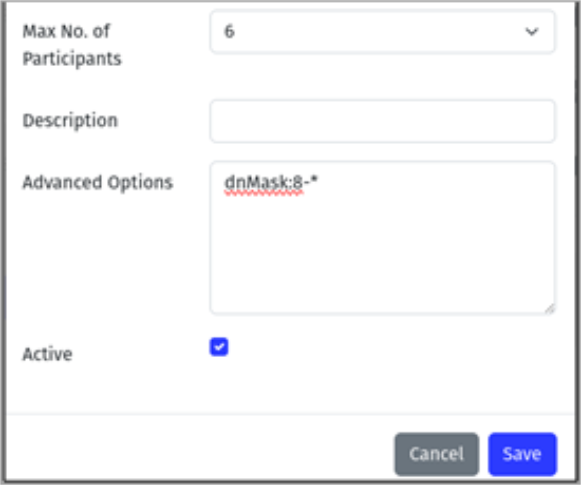
The syntax 8-* instructs VidyoGateway to replace the last eight digits with an asterisk:- Before masking: +13366666666
- After masking: +133********
- Click Save to save the display name mask.
Activate and deactivate services
You can also activate or deactivate a service by selecting or clearing the Active checkbox from its corresponding Add or Edit Service pop-up. For more information, see Add a service.
To activate or deactivate a service:
- Log in to the Admin portal using your System Console account. The General > VidyoPortal page displays by default.
- Click the SERVICES tab.
- Click the corresponding Check Mark button to the right of the list of services to activate or deactivate a service.

If desired, you can also select the Edit or Delete buttons. - Click Apply Changes on the Services tab if desired.
- Any services you edit, delete, activate, and deactivate accrue until you click Apply Changes, and then all your Service changes are applied to your VidyoGateway server.
- When clicked, a pop-up informs you that the change drops all the active conference calls on your VidyoGateway server.
Delete a service
If you permanently delete a service from your system, it cannot be undone.
To delete a service:
- Log in to the Admin portal using your System Console account. The General > VidyoPortal page displays by default.
- Click the SERVICES tab.
- Click the corresponding Delete icon to the right of the list of services to delete a service. The Delete Service pop-up displays.
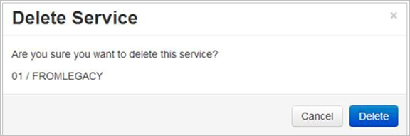
- Click Delete.
- Click Apply Changes on the Services tab if desired.
- Any services you edit, delete, activate, and deactivate accrue until you click Apply Changes, and then all your service changes are applied to your VidyoGateway server.
- When clicked, a pop-up informs you that the change drops all the active conference calls on your VidyoGateway server.

Edit a service
To edit a service:
- Log in to the Admin portal using your System Console account. The General > VidyoPortal page displays by default.
- Click the SERVICES tab.
- Click the corresponding Edit icon to the right of the list of services to edit a service. The Edit Service pop-up displays.
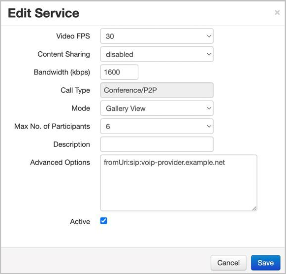
- Modify your service as desired. For more information about how to edit any of the fields on this dialog box, see Add a service.
- Click Save in the Edit Service pop-up. If desired, you can also select the Delete, Activate, and Deactivate buttons.
- Click Apply Changes on the Services tab if desired.
- Any services you edit, delete, activate, and deactivate accrue until you click Apply Changes, and then all your Service changes are applied to your VidyoGateway server.
- When clicked, a pop-up informs you that the change drops all the active conference calls on your VidyoGateway server.

Call types and service examples
The following call types and service examples are provided your reference. They include examples for H.323, SIP, Incoming URI Dialing, Legacy H.323, and TCS4 Delimiters.
|
Note The dialing examples mention service prefixes. Services enable the creation of default prefixes; meaning, when a given service is selected, the default prefix set for the service is used without having to include it when dialing through VidyoGateway. For more information, see Manage services. |
H.323 outgoing call examples
|
Note All outgoing H.323 calls are P2P connections if dialed from a Vidyo user’s home page. For conferences or multipoint connections, you must be added via invitation from the Control Meeting or Admin Page functions. |
An outgoing VidyoGateway call (with a gatekeeper) to an H.323 endpoint:
- [VidyoGateway Outgoing service prefix] + [H.323 endpoint extension]
- Example: 039001
An outgoing VidyoGateway call (with a gatekeeper) to an MCU/bridge conference endpoint:
- [VidyoGateway Outgoing service prefix] + [MCU conference ID]
- Example: 034001
An outgoing VidyoGateway call (without a gatekeeper) to an H.323 endpoint:
- [VidyoGateway Outgoing service prefix] + [IP Address of H.323 system]
- Example: 03192.167.1.2
An outgoing VidyoGateway call (without a gatekeeper) to an MCU/bridge conference endpoint:
- [VidyoGateway Outgoing service prefix] + [MCU conf ID]@[IP Address of MCU]
- Example: 032001@192.168.1.2
In this example, utilize H.323 URL dialing (Annex 0) to directly dial into an MCU conference.
- Example: 032001@192.168.1.2
H.323 incoming call examples
Service prefixes can be used to set all your incoming calls as either P2P or Conference, as desired. For more information, see Manage services.
An incoming VidyoGateway call (with a gatekeeper) from an H.323 endpoint:
- [VidyoGateway Incoming service prefix] + [Vidyo extension]
- Example: 035001
An incoming VidyoGateway call (without a gatekeeper) from a Codian MCU endpoint:
- [VidyoGateway IP Address]![VidyoGateway incoming service prefix] + [Vidyo username or extension]
- Example: 192.168.1.110!035001
An incoming VidyoGateway call (without a gatekeeper) from an H.323 endpoint:
- [VidyoGateway IP Address] + [TCS4 delimiter]+[VidyoGateway imcoing service prefix]+[Vidyo extension]
- Example: 192.168.1.110##035001
- Example: 192.168.1.110##035001
|
Note This example is for Polycom and Lifesize endpoints using ## as the TCS4 delimiter. For additional delimiter examples, see TCS4 delimiters. |
SIP incoming call using a prefix example
Service prefixes can be used to set all your incoming calls as either P2P or Conference, as desired. For more information, see Manage services.
An incoming VidyoGateway call from a SIP endpoint:
- [VidyoGateway Incoming service prefix] + [Vidyo username or extension]@[VidyoGateway IP Address]
- Example: 075001@192.168.1.11
SIP incoming URI dialing example
[jsmith@examplecompany.com] Where jsmith is a member of the tenant named “tenant1.”
|
Note The SIP SRV record FQDN must be configured as [examplecompany.com] and it must be configured by your network administrator to point to the VidyoGateway IP address (Standalone or Cluster). For more information, refer to your SIP equipment documentation. For multi-tenant systems, you must associate [examplecompany.com] to Tenant1. To do this, configure the Tenant VidyoGateway SIP/H.323 SRV record FQDN field to your [examplecompany.com] FQDN in the Super portal as part of the “tenant1” configuration. |
For more information, refer to "Manage tenants as the Super Admin" in the VidyoPortal and VidyoRouter Administrator Guide.
For more information about SIP URI configuration, see Configure the VidyoPortal settings.
Dial from an H.323 endpoint into a Vidyo PIN-protected room
[VidyoGateway IP Address ] + [TCS4 delimiter] + [VidyoGateway service prefix] + [Vidyo extension] + [VidyoGateway PIN delimiter] + [Vidyo Users Room PIN]
Example: 192.168.1.110##035001*1234 (This is a Polycom Lifesize call string coming into a Vidyo PIN protected room.)
|
Note The VidyoGateway PIN delimiter can be set on the VidyoGateway Configuration page. The default is an asterisk *. |
TCS4 delimiters
The following are examples of TCS4 delimiters for various endpoints.
- Polycom and Lifesize endpoints use ##:
- Example: 192.168.1.110##035001
- Polycom PVX v.8.0.4 uses @:
- Example: 035001@192.168.1.110
- Sony uses #:
- Example: 192.168.1.110#035001
- Tandberg/Cisco does not support TCS4 delimiters, but uses @ as an inverted format URL (Annex 0) style (however, Tandberg C releases TC4.1.2 or later accept the name@domain or name@IPAddress dialing formats without being registered to a gatekeeper):
- Examples: 035001@192.168.1.110,h323:35001@192.168.1.110
- Tandberg 2500 vB3.9 and Tandberg MCU 8+8 endpoints use ,:
- Examples: 192.168.1.110,035001
- Codian MCI uses !:
- Example: 192.168.1.110!035001
Configure Integrated Voice Response (IVR) sets
IVR is not available if Video Loopback is enabled. For more information, see Configure video loopback settings.
When you dial into VidyoGateway from a H.323/SIP device, a system of menus complete with text and voice prompts guide you through the IVR interfaces. You can configure these IVR interfaces using settings for Parameters, Prompts, and Import/Export IVR Media and Prompt Settings on the corresponding tabs.
The following DTMF Modes are supported by Vidyo’s IVR functions:
- H.245 signal (tone) outband
- H.245 alphanumeric (string) outband
- RFC2833 (SIP Signaling with RTP payload)
- PCM waveform inband
IVR prompts are initially disabled by default.
Enable your IVR settings
At least one service with From Legacy as the Direction must be set as the default to use IVR. For more information about the Default service setting, see Add a service.
If you are clustering your VidyoGateways and choose to enable IVR, you must enable it on your Active Controller, Standby Controller, and all your Cluster Nodes. Moreover, if you choose to customize the IVR settings, you must configure those on all the VidyoGateway servers in the cluster (Active Controller, Standby Controller, Cluster Nodes). For more information about clusters, see Configure clusters.
To enable your IVR settings:
- Log in to the Admin portal using your System Console account. The General > VidyoPortal page displays by default.
- Click the IVR tab. The IVR > General page displays by default.
- Click Enable IVR after making all your desired settings on the General, Appearance, Instructions, and Prompts subtabs. When clicked, a system notification indicates the IVR is now enabled (or disabled).
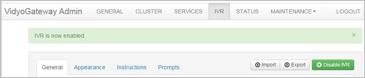
Note
The feature toggles between enable and disable states.
The Enable IVR button is shown along with the Import and Export buttons on the upper-right of the IVR tab. For more information, see Import and export VidyoGateway IVT media and prompt settings.
Configure General IVR settings
To configure your General IVR settings:
- Log in to the Admin portal using your System Console account. The General > VidyoPortal page displays by default.
- Click the IVR tab. The IVR > General page displays by default.
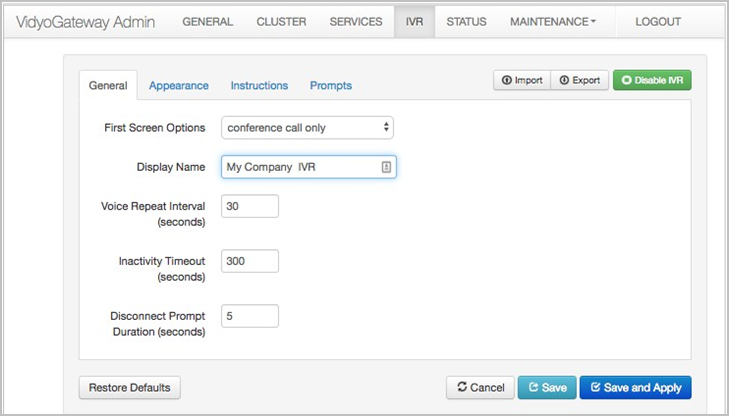
- Enter General settings for your IVR. Available choices include the following:
- Select one of the following notification types from the First Screen Options drop-down to be first shown from your VidyoGateway server IVR Interface:
- Select call type selection to make both conference and direct calls available from the first screen. The Select Call Type notification displays. For more information about the Select Call Type notification, see VidyoGateway IVR screen prompt types.
- Select conference call only to make only conference calls available from the first screen. The Enter Conference Extension notification displays. For more information about the Enter Conference Extension notification, see VidyoGateway IVR screen prompt types.
- Select direct call only to make only direct calls available from the first screen. The Enter Direct Call Extension notification displays. For more information about the Enter Direct Call Extension notification, see VidyoGateway IVR screen prompt types.
Note
When placing a direct call and the remote participant has not answered, use the * key to cancel the call. For more information, see VidyoGateway IVR screen instruction type.
- Enter the name of your VidyoGateway in the Display Name field to be shown when calling in from H.323/SIP devices.
- Enter a numeric time value (in seconds) in the Voice Repeat Interval (seconds) field to elapse between repeated voice responses.
- Enter a numeric time value (in seconds) in the Inactivity Timeout (seconds) field to elapse before a H.323/SIP endpoint is disconnected from your VidyoGateway due to inactivity.
- Enter a numeric time value (in seconds) in the Disconnect Prompt Duration (seconds) field to elapse from when a H.323/SIP endpoint is disconnected from your VidyoGateway due to inactivity until being returned to the VidyoGateway IVR screen.
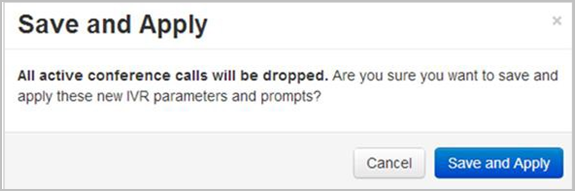
- Click Save or Save and Apply as desired.
- When you click Save and Apply, a pop-up informs you that the change drops all the active conference calls on your VidyoGateway server.
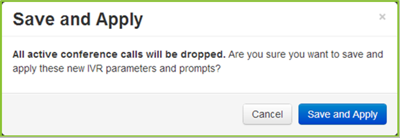
- Settings made while only clicking Save accrue and are applied when you subsequently click Save and Apply or reboot your VidyoGateway server.
- When you click Save and Apply, a pop-up informs you that the change drops all the active conference calls on your VidyoGateway server.
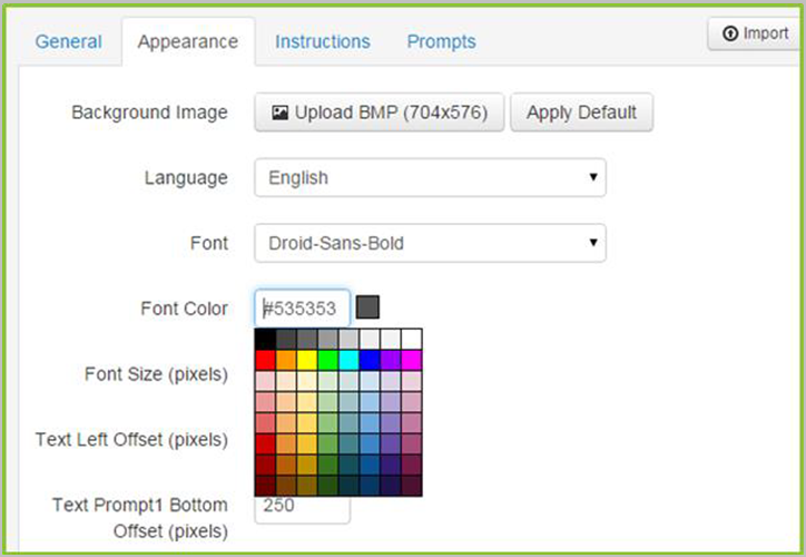
Configure Appearance IVR settings
To configure your Appearance IVR settings:
- Log in to the Admin portal using your System Console account. The General > VidyoPortal page displays by default.
- Click the IVR tab. The IVR > General page displays by default.
- Click the Appearance subtab.
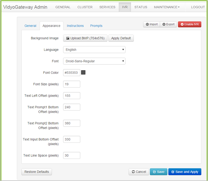
- Use the following two buttons to select a custom image or use the default for your VidyoGateway IVR background image:
- Click Upload BMP to select a custom image for use on your VidyoGateway IVR. Your .bmp file must be 704 x 576 and not exceed 10 MB.
- Click Apply Default to apply the default background image to your VidyoGateway IVR.
- Click the Language drop-down and select the interface language for your IVR.
- Click the Font drop-down and select the font you want to use for the text shown on your IVR interface.
- Click the Font Color field and select from the palate of swatch colors that displays.
Note
You can enter a standard color name or hexadecimal value directly in the field.
Hexadecimal color values are shown as you mouse-over swatches on the palate.
A swatch of the selected color is shown to the right of the field.
- Enter a number value (in pixels) for the Font Size you want used for your VidyoGateway IVR screens.
- Enter a number value (in pixels) for the Text Left Offset (the margin between the left of the screen and the start of your text) you want used for your VidyoGateway IVR.
The following screenshot shows the text left offset (and other offset values) on the VidyoGateway IVR screens: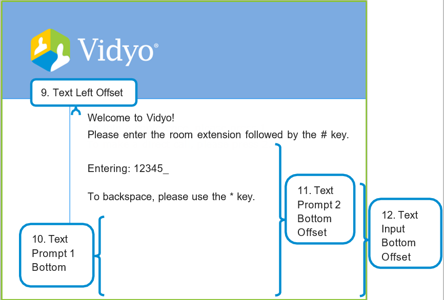
- Enter a number value (in pixels) for the Text Prompt 1 Bottom Offset (the space between the bottom and the start of your text in the first dialog box shown) you want used for your VidyoGateway IVR screens.
- Enter a number value (in pixels) for the Text Prompt 2 Bottom Offset (the space between the bottom and the start of your text in the second dialog box shown) you want used for your VidyoGateway IVR screens.
- Enter a number value (in pixels) for the Text Input Bottom Offset (the space between the bottom and the start of your text in the first input dialog box shown) you want used for your VidyoGateway IVR screens.
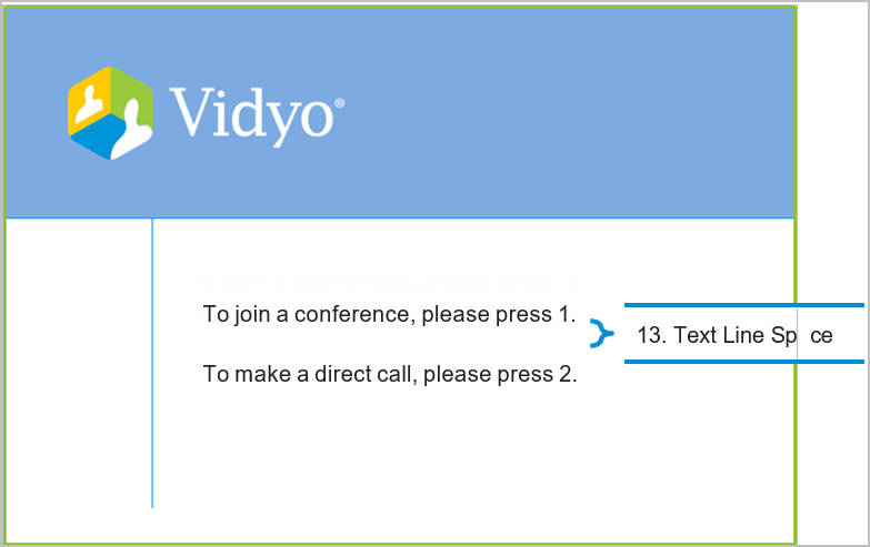
- Enter a number value (in pixels) for the Text Line Space (the space between lines of text) you want used for your VidyoGateway IVR screens. The following screenshot shows the line space on the VidyoGateway IVR screen:
- Click Save or Save and Apply as desired.
- When you click Save and Apply, a pop-up informs you that the change drops all the active conference calls on your VidyoGateway server.
- Settings made while only clicking Save accrue and are applied when you subsequently click Save and Apply or reboot your VidyoGateway server.
- When you click Save and Apply, a pop-up informs you that the change drops all the active conference calls on your VidyoGateway server.
Configure VidyoGateway IVR screen instruction settings
To configure your VidyoGateway IVR screen instruction settings:
- Log in to the Admin portal using your System Console account. The General > VidyoPortal page displays by default.
- Click the IVR tab. The IVR > General page displays by default.
- Click the Instructions subtab.
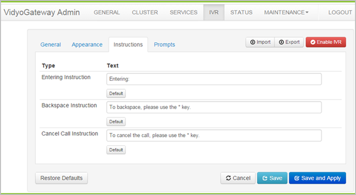
- Enter custom text you want used for your VidyoGateway IVR screens in the Entering Instruction field.
Entering Instruction is the announcement used when participants dialing from a H.323/SIP device to join video conferences.Note
Click Default at any time to restore the original system text for the corresponding instruction.
The following screenshot shows the entering instruction for the VidyoGateway IVR screen: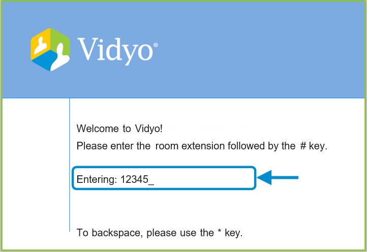
- Enter custom text you want used for your VidyoGateway IVR screens inthe Backspace Instruction field.
The Backspace Instruction is what participants dialing from H.323/SIP devices are told to move backward through menu selections.Note
Click Default at any time to restore the original system text for the corresponding instruction.
The following screenshot shows the backspace instruction for the VidyoGateway IVR screen: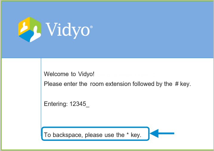
- Enter custom text you want used for your VidyoGateway IVR screen in the Cancel Call Instruction field.
- The Cancel Call Instruction is what participants dialing from H.323/SIP devices are told to immediately end their call.
Note
Click Default at any time to restore the original system text for the corresponding instruction.
The following screenshot shows the cancel call instruction for the VidyoGateway IVR screen: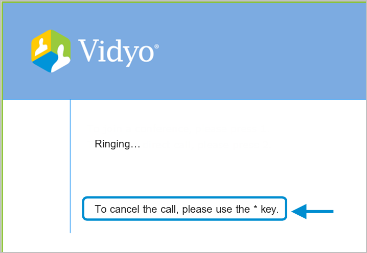
- Click Save or Save and Apply as desired.
- When you click Save and Apply, a pop-up informs you that the change drops all the active conference calls on your VidyoGateway server.

- Settings made while only clicking Save accrue and are applied when you subsequently click Save and Apply or reboot your VidyoGateway server.
- When you click Save and Apply, a pop-up informs you that the change drops all the active conference calls on your VidyoGateway server.
VidyoGateway IVR screen instruction type
VidyoGateway IVR screen instruction types include the following:
- The Entering Instruction prompt type: This prompt is shown when you start entering the number to complete the extension entry.
- The Backspace Instruction prompt type: This prompt is shown when you start entering room or direct extensions or pins. It displays text instructing you to use the * key as a backspace.
- The Cancel Call Instruction prompt type: This prompt is when you are in the process of connecting to a conference room. It displays text instructing you to use the * key to cancel the call.
Configure VidyoGateway IVR screen prompt settings
To configure your VidyoGateway IVR screen prompt settings:
- Log in to the Admin portal using your System Console account. The General > VidyoPortal page displays by default.
- Click the IVR tab. The IVR > General page displays by default.
- Click the Prompts subtab.
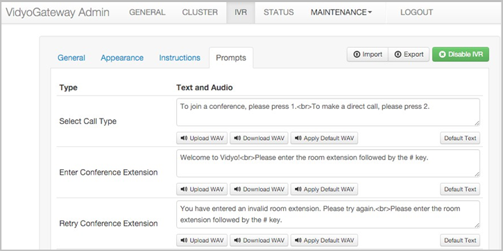
Note
The previous screenshot has been altered to show a condensed listing of the IVR prompt types. For a complete list of IVR prompt types and descriptions, see VidyoGateway IVR screen prompt types.
- Enter settings for each IVR prompt type using the following corresponding fields:
- Enter custom prompt type text in the corresponding field.
Note
Click and drag the lower-right corner of the Prompt type field to adjust the space to the size desired.
- Click Default Text to use the original system text for the corresponding VidyoGateway IVR screen prompt type.
- Click Upload WAV to select a custom sound file for use on your VidyoGateway IVR screen prompt type. You must upload a 16-bit, mono .wav file.
- Click Download WAV to save the sound file being currently used as your VidyoGateway IVR screen prompt type.
- Click Apply Default WAV to use the original system sound file as your VidyoGateway IVR screen prompt type. For a complete list of IVR prompt types and descriptions, see VidyoGateway IVR screen prompt types.
- Enter custom prompt type text in the corresponding field.
- Click Save or Save and Apply as desired.
- When you click Save and Apply, a pop-up informs you that the change drops all the active conference calls on your VidyoGateway server.
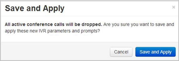
- Settings made while only clicking Save accrue and are applied when you subsequently click Save and Apply or reboot your VidyoGateway server.
- When you click Save and Apply, a pop-up informs you that the change drops all the active conference calls on your VidyoGateway server.
VidyoGateway IVR screen prompt types
VidyoGateway IVR screen prompt types include the following:
- The Select Call Type prompt type. If configured as the First Screen Option selection as described in Configure General IVR settings, you first dial in to VidyoGateway and receive this prompt showing choices to join a conference and make a direct call. The following screenshot shows the Select Call Type prompt for the VidyoGateway IVR screen:
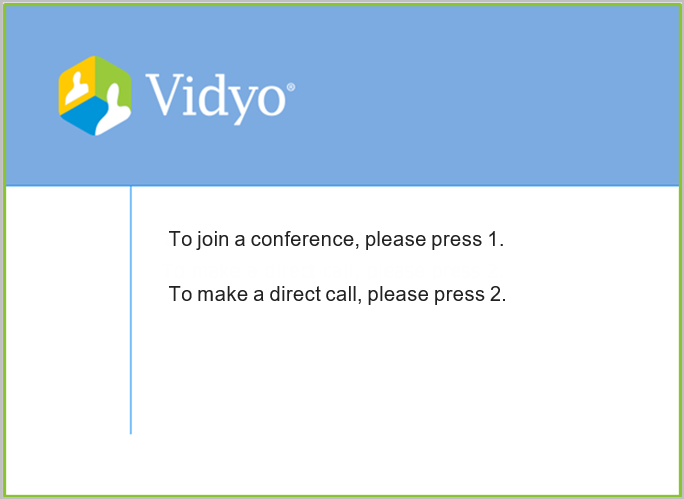
- The Enter Conference Extension prompt type. If configured as the First Screen Option selection in Configure Appearance IVR settings, you first dial in to VidyoGateway and receive this prompt asking you to enter the room extension followed by the # key.
- The Retry Conference Extension prompt type. If you choose to join a conference and enter an invalid room extension, this prompt tells you and asks you to try again by entering the room extension followed by the # key.
- The Retry Room not Accessible (Locked or Full) prompt type. If you lock the room at any point or the room has reached its capacity based on the maximum number of participants set in the VidyoPortal Admin UI, this prompt tells you the conference room is not available and to try again later.
- The Retry Room Generic Error prompt type. If you are unable to join a conference for reasons other than being locked out, this prompt is the generic message indicating you were unable to join the conference and to try again by entering the room extension followed by the # key.
- The Enter Conference Pin prompt type. If you choose to join a conference and enter a room extension followed by the # key, this prompt then instructs you to enter a room pin followed by the # key.
- The Retry Conference Pin prompt type. If you choose to join a conference, enter a room extension followed by the # key, and enter an incorrect room pin followed by the # key, this prompt tells you and asks you to try again by entering the room pin followed by the # key.
- The Enter Direct Call Extension prompt type. If configured as the First Screen Option selection as described in Configure Appearance IVR settings, you first dial in to VidyoGateway and receive this prompt asking you to enter the extension followed by the # key.
- The Retry Direct Call Extension prompt type. If you choose to make a direct call and enter an invalid extension, this prompt tells you and asks you to try again by entering the extension followed by the # key.
- The Retry Direct Call (Offline) prompt type. If you choose to make a direct call, enter an extension, and the remote party is offline, this prompt tells you and asks you to try again by entering the extension followed by the # key.
- The Retry Direct Call (Busy) prompt type. If you choose to make a direct call, enter an extension, and the remote party’s line is busy, this prompt tells you and asks you to try again by entering the extension followed by the # key.
- The Retry Direct Call (No Answer) prompt type. If you choose to make a direct call, enter an extension, and the remote party does not answer, this prompt tells you and asks you to try again by entering the extension followed by the # key.
- The Retry Direct Call (Reject) prompt type. If you choose to make a direct call, enter an extension, and the remote party rejects the call, this prompt tells you and asks you to try again by entering the extension followed by the # key.
- The Retry Direct Call (Generic Error) prompt type. If you choose to make a direct call, enter an extension, and it’s not connected for any other reason than the previous 4 mentioned, this prompt tells you the remote party could not be reached and asks you to try again by entering the extension followed by the # key.
- The Retry Direct Call (Cancel) prompt type. If you choose to make a direct call, enter an extension, and it’s cancelled, this prompt tells you and asks you to try again by entering the extension followed by the # key.
- The Direct Call Ringing prompt type. If you choose to make a direct call, enter an extension, and the line is ringing, this prompt indicates that the line is ringing.
- The Only Participant prompt type. If you choose to join a conference, enter a room extension followed by the # key, enter a room pin followed by the # key, and join successfully, you are shown this prompt if you are the only participant in the conference.
Import and export VidyoGateway IVR media and prompt settings
You can apply or restore IVR media and prompt settings that have been already saved by importing an existing .tar.gz file to your VidyoGateway server. You can also save exported settings to a .tar.gz file for applying to a different VidyoGateway server or just keep it as a backup.
|
Note Imported and exported settings only apply to media files and prompts. It does not include other IVR configurations. |
Import IVR media and prompt settings
To import IVR media and prompt settings:
- Log in to the Admin portal using your System Console account. The General > VidyoPortal page displays by default.
- Click the IVR tab. The IVR > General page displays by default.
- Click Import. The Import IVR Configuration pop-up displays.
- Click Choose File to locate the configuration file.
- Click Import. A system notification indicates the IVR configuration was imported successfully.
Export IVR media and prompt settings
To export IVR media and prompt settings:
- Log in to the Admin portal using your System Console account.
- Click the IVR tab. The IVR > General page displays by default.
- Click Export. Your browser downloads a .zip file which contains 19 .wav files, a text file, and a .bmp file.
Enable and disable VidyoGateway IVR settings
So far you’ve been making configurations on the General, Appearance, Instructions, and Prompt subtabs and clicking Save or Save and Apply as desired. However, clicking Enable or Disable IVR is what determines whether your VidyoGateway IVR screen is actually shown to users accessing VidyoConferences via H.323/SIP devices.
To enable or disable VidyoGateway IVR settings:
- Log in to the Admin portal using your System Console account. The General > VidyoPortal page displays by default.
- Click the IVR tab. The IVR > General page displays by default.
- Click Enable IVR. This button toggles between the Enable and Disable functions.
Check the status of your VidyoGateway
The STATUS page displays the network connectivity status of the VidyoGateway with the VidyoPortal, the VidyoManager, and a SIP Trunk, if configured. The status displays as “OK” or “FAIL” depending on whether the VidyoPortal, VidyoManager, and SIP Trunk are successfully connected.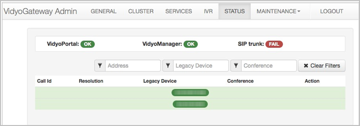
When accessing the VidyoGateway Admin Pages for the Active Controller, the connection status for each node that is configured for the VidyoGateway cluster on the Cluster > Nodes subtab display on the Status page as well. For more information, see Configure nodes for the active controller in cluster mode.
|
Note When configuring your VidyoGateways as a cluster, you must export the pre-shared key from your Active Controller and import it into your Standby Controller and Cluster Nodes. Otherwise, calls on your Standby Controller or Cluster Nodes will not be visible from the Status tab in your Active Controller. |
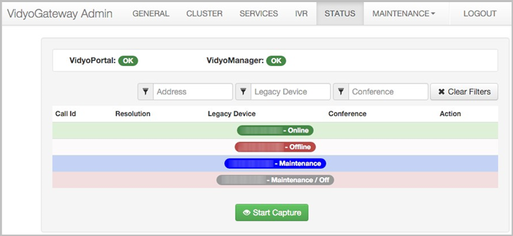
If the VidyoGateway is processing calls, the main area of the screen is populated with call information such as Call ID, Resolution, Legacy Device, and Conference.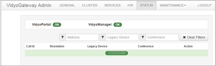
If the VidyoGateway is not currently processing calls, no results display like the screenshot previously shown.
When results do display on the screen, they can be filtered by the following:
- In the Address filter, you can filter results by IP of Cluster.
- In the Legacy Device filter, you can filter results by IP of H.323/SIP devices.
- In the Conference filter, you can filter by conference room names already set up in your system.
Click Clear Filters to instantly remove any parameters you provided.
View call statistics
To view call statistics:
- Log in to the Admin portal using your System Console account. The General > VidyoPortal page displays by default.
- Click the STATUS tab.
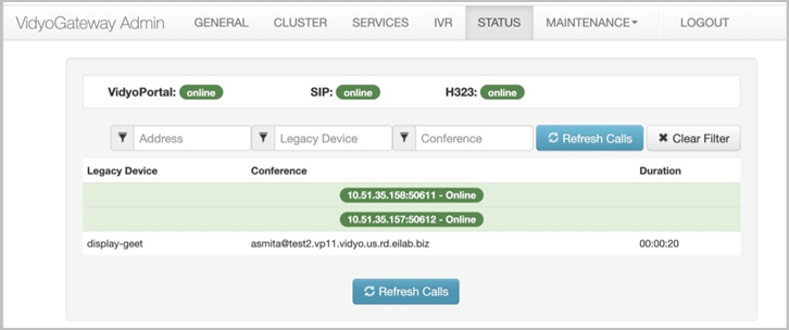
- If the VidyoGateway is not currently processing calls, no results display on the screen.
- If your VidyoGateway is processing calls, the main area of the screen is populated with call information such as Legacy Device, Conference, and Call Duration as follows.
- Click the magnifying glass to the right of a specific call row in the main area of the screen to view more statistics about that call. The Call Statistics pop-up displays.
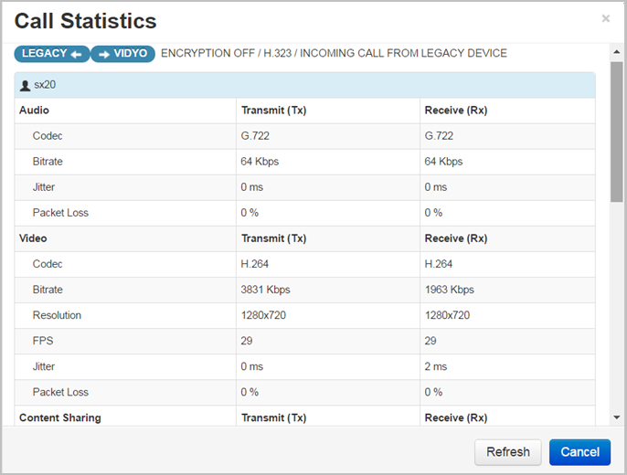
- The following information is available on the Call Statistics pop-up:
- The Legacy ←→ Vidyo label is shown along with the encryption status, codec, and call direction.
- The Legacy device shaded table heading displays the name of your device along with the following data between the VidyoGateway and the Legacy device:
- Audio codec protocols being used for both transmitting and receiving messages.
- Audio bitrate for both transmitting and receiving values (in Kbps).
- Audio jitter for both transmitting and receiving values (in ms).
- Audio packet loss for both transmitting and receiving values (as a percent).
- Video codec protocols for both transmitting and receiving messages.
- Video bitrate for both transmitting and receiving values (in Kbps).
- Video resolution dimensions for both transmitting and receiving values (in pixels).
- Video frames per second (FPS) for both transmitting and receiving values.
- Audio jitter for both transmitting and receiving values (in ms).
- Packet loss for both transmitting and receiving values (as a percentage).
- Content sharing codec protocols for both transmitting and receiving messages.
- Content sharing bitrate for both transmitting and receiving values (in Kbps).
- Content sharing resolution dimensions for both transmitting and receiving values (in pixels).
- Content sharing frames per second (FPS) for both transmitting and receiving values.
- Content sharing jitter for both transmitting and receiving values (in ms).
- Content sharing packet loss for both transmitting and receiving values (as a percentage).
- The Vidyo ←→ Legacy label is shown along with the encryption status.
- The Vidyo device shaded table heading displays the name of your device along with data between the VidyoGateway and the VidyoRouter.
- Click the X button on the right of a row to drop the call.
- Click Refresh to reload the statistical data showing on Call Statistics.
Perform diagnostics
The Maintenance > Diagnostics page allows you to run and download system logs for debugging analysis, as well as download audit logs.
Specific user activity audit log files may also be downloaded from the Maintenance > Diagnostics page using the Download Audit Logs button. For more information about downloading and viewing audit logs, see Audit.
Capture and download system logs
To capture and download system log files for debugging purposes:
- Log in to the Admin portal using your System Console account. The General > VidyoPortal page displays by default.
- Navigate to MAINTENANCE > DIAGNOSTICS. The Maintenance > Diagnostics > Logs page displays by default.
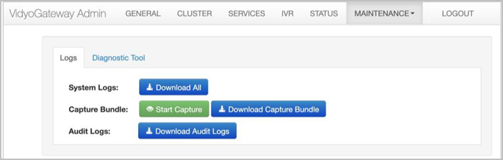
- Click Download All if you want to download all the current system logs; otherwise, skip this step and proceed to the next step.
- Click Start Capture. The Start Capture pop-up displays.
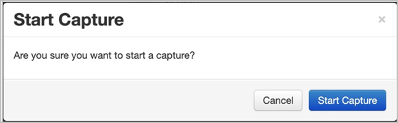
- Click Start Capture. The logs of calls taking place on your system are then recorded into a file, and a message appears indicating that the capture started successfully.
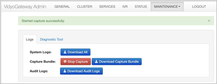
- Click Stop Capture when you want to stop capturing logs of the calls taking place on your VidyoGateway. The Stop Capture pop-up displays.
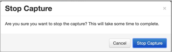
- Click Stop Capture. When the capture is stopped, a message appears indicating it was stopped successfully.
- Click Download Capture Bundle to download the logs that you captured. The Enter password to protect downloaded files pop-up displays.
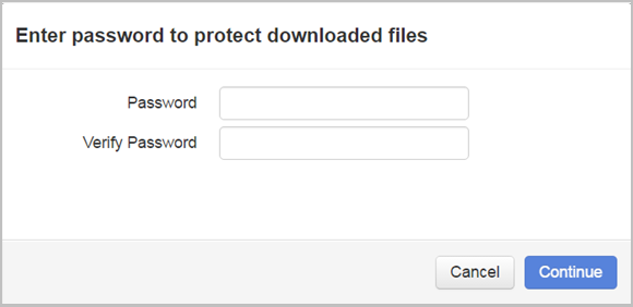
- Enter a password in the Password field.
- Re-enter the password in the Verify Password field.
- Click Continue. Your browser downloads a .tar.gz file containing the log file bundle for debugging analysis.
Run diagnostic logs
You can analyze your system health by creating a system diagnostic file and viewing the results. Depending on your system, the diagnostic file shows the following information:
- Date
- Type of Node and version
- Machine Type
- Node FQDN
- IP Address
- Server Mode
- DNS Server Report
- Ethernet Hardware Report
- VidyoGateway Ports
- System Status Report
- Certificate Check
To run diagnostic logs:
- Log in to the Admin portal using your System Console account. The General > VidyoPortal page displays by default.
- Navigate to MAINTENANCE > DIAGNOSTICS. The Maintenance > Diagnostics > Logs page displays by default.
- Click the Diagnostic Tool subtab.
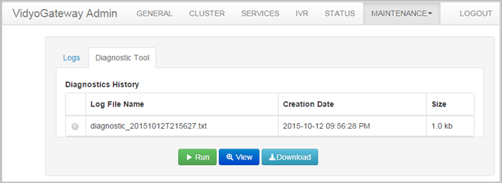
- Click Run. Wait a few mintes for the diagnostic file to generate and display in the Diagnostics History table.
View diagnostic logs
To view diagnostic log files for debugging purposes:
- Log in to the Admin portal using your System Console account. The General > VidyoPortal page displays by default.
- Navigate to MAINTENANCE > DIAGNOSTICS. The Maintenance > Diagnostics > Logs page displays by default.
- Click the Diagnostic Tool subtab.
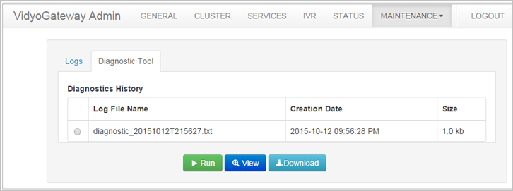
- Select the radio button to the left of the log file that needs to be viewed.
- Click View. The View Diagnostic Logs pop-up displays.
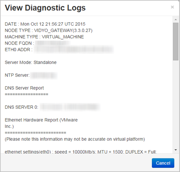
- Click Cancel to close the pop-up.
Download diagnostic logs
To download diagnostic log files for debugging purposes:
- Log in to the Admin portal using your System Console account. The General > VidyoPortal page displays by default.
- Navigate to MAINTENANCE > DIAGNOSTICS. The Maintenance > Diagnostics > Logs page displays by default.
- Click the Diagnostic Tool subtab.
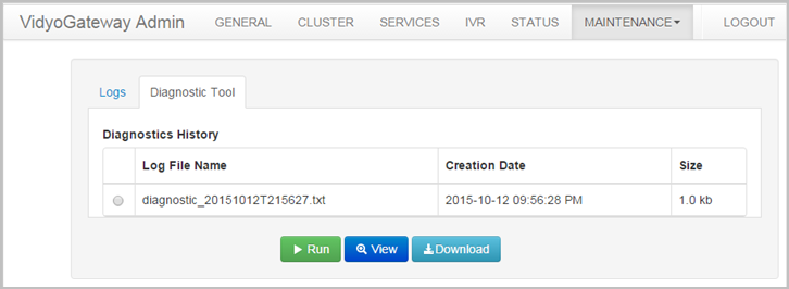
- Select the radio button to the left of the log file that needs to be viewed.
- Click Download. Your browser downloads a .tar.gz file containing your log file.
Configure a public IP address and view your VidyoGateway network sets
The Maintenance > Network page allows you to configure a public IP address and enable Static NAT mode (if desired), as well as view network settings for your VidyoGateway server.
If you need to configure your network settings, use the System Console. For more information, see Configure your server via the System Console.
Configure a public IP address and enable Static NAT mode
Only configure the public IP address on your Controller nodes if you want to dial in to your VidyoGateway using your FQDN.
|
Note Public IP address configuration is intended for use on a VidyoGateway when it’s deployed behind a NAT. The public IP address should be the address returned by your DNS when looking up the FQDN for your cluster. Configuring your public IP address only works when the cluster has a private IP address (NAT). |
For example, if examplecompany.examplegateway.com points to 1.2.3.4, and 1.2.3.4 is configured in your firewall as the H.323 address, then you would enter 1.2.3.4 in the Public IP Address field.
To configure a public IP address:
- Log in to the Admin portal using your System Console account. The General > VidyoPortal page displays by default.
- Navigate to MAINTENANCE > NETWORK.
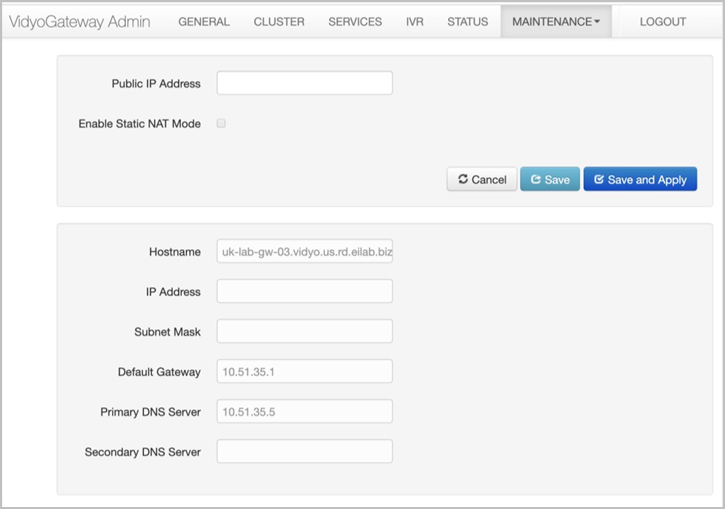
- Enter your public IP Address in the Public IP Address field.
Note
The public IP address should be the address returned by your DNS when looking up the FQDN for your cluster. Configuring your public IP address only works when the cluster has a private IP address (NAT).
For example, if examplecompany.examplegateway.com points to 1.2.3.4, and 1.2.3.4 is configured in your firewall as the H.323 address, then you would enter 1.2.3.4 in the Public IP Address field.
- Select the Enable Static NAT Mode checkbox if you want to enable a static NAT. A static NAT is a type of NAT in which a private IP address is mapped to a public IP address, where the public address is always the same IP address (i.e., it has a static address). This allows an internal host, such as the VidyoGateway, to have an unregistered (private) IP address and still be reachable over the Internet.
- Click Save or Save and Apply as desired.
- When you click Save and Apply, a pop-up informs you that the change drops all the active conference calls on your VidyoGateway server.
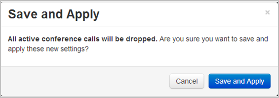
- Settings made while only clicking Save accrue and are applied when you subsequently click Save and Apply or reboot your VidyoGateway server.
- When you click Save and Apply, a pop-up informs you that the change drops all the active conference calls on your VidyoGateway server.
View your VidyoGateway network settings
The Maintenance > Network page enables you to quickly view your VidyoGateway network settings. If you need to configure your network settings, use the System Console. For more information, see Configure your server via the System Console.
To view your VidyoGateway server network settings:
- Log in to the Admin portal using your System Console account. The General > VidyoPortal page displays by default.
- Navigate to MAINTENANCE > NETWORK.
- View your VidyoGateway network settings, including your hostname, IP address, subnet mask, and more.
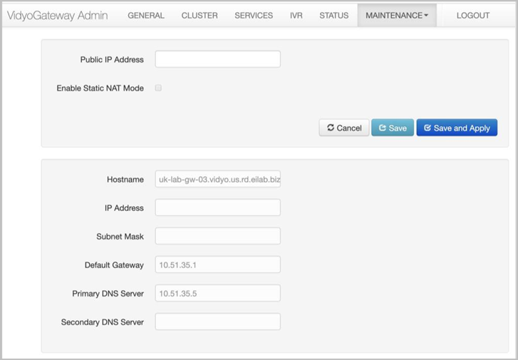
Secure your VidyoGateway with SSL and HTTPS
This section describes how to secure your VidyoGateway. For more information about securing your entire video conferencing system, refer to the Security appendix in the VidyoPortal and VidyoRouter Administrator Guide.
Before securing the VidyoGateway, it’s important to understand there are two security layers available for your video conferencing system:
- HTTPS – The web standard involves setting up HTTPS and using Secure Socket Layer (SSL). This ensures secure browsing on VidyoGateway.
- While support for HTTPS is standardly included in Vidyo products, it does require the purchase and/or acquisition of SSL certificate(s) from a valid CA (Certificate Authority). You may implement HTTPS without enabling Vidyo’s Encryption to implement secure browsing only.
- Enabling HTTPS secure browsing establishes secure connections between browsers and VidyoGateway Admin portal.
- HTTPS uses standard SSL certification to provide secured browsing to these web pages, protecting usernames and passwords, and actions performed on the pages. Confidential information shared during a VidyoGateway browsing session is protected from phishing and hacking attempts.
- Encryption – This is an additionally purchased Vidyo licensed feature which provides encrypted endpoint management, signaling and media for end-to-end security for your entire video conferencing system.
Note
This feature is first enabled on your VidyoPortal, and then on your VidyoGateway.
Encryption is meant to be implemented in addition to (and not in place of) HTTPS. This software option still requires the implementation of HTTPS including the purchase and/or acquisition of SSL certificate(s) from a valid CA (Certificate Authority). Once encryption is enabled, all calls are secured and encrypted for all users and components. Mixing secured and non-secured calls is not currently supported.
Encrypted end-to-end security uses AES-128 encryption to secure the connection between the VidyoPortal and the VidyoRouter.
Confidential information shared during a video conference is protected from hijacking and eavesdropping attempts.
VidyoGateway SSL and HTTPS security procedure overview
To secure your VidyoGateway system by enabling HTTPS, you must complete specific configurations done on six sequential subtabs from left to right in the Maintenance > Security section of the VidyoGateway Admin portal. The subtabs include:
- The Private Key subtab is for generating or uploading an SSL private key.
- The CSR subtab is for generating an SSL Certificate Signing Request (CSR).
- The Server Cert subtab is for deploying your server certificate.
- The Server CA Cert subtab is for deploying your server Certification Authority (CA) certificates.
- The Ports subtab is for correctly configuring the HTTPS port setting to 443. This subtab is also used for Management Interface configurations. For more information, see Configure your Vidyo server’s Management Interface and port.
- The Advanced subtab is for deploying your Client Root CA certificates. The Advanced subtab is also used to upload and import security settings, and reset security settings. For more information, see Import Client Root CA Certificates from the Advanced tab, Import certificates from a certificate bundle, and Export a security bundle containing your certificate configuration.
You can then enable HTTPS on your VidyoGateway. However, do not use Enabling HTTPS and Enabling HTTPS Only until you’ve completed all the previous steps for securing your VidyoGateway system. For more information, see Enable HTTPS on your Vidyo server.
The following sections explain these steps in detail.
Import, export, and regenerate an SSL private key
The following procedures show you how to import, export, and regenerate an SSL Private Key.
An initial key with a 2048 key size is automatically generated when you first set up your system. When regenerating, examine your own security requirements and applicable policies carefully before deciding on a suitable key size.
Import an SSL private key
Private keys can be imported into your server. We recommend carefully backing up your existing SSL Private Key in its entirety before starting SSL Private Key procedures.
|
Note To import an SSL private key, you must first disable HTTPS. You can only import encrypted and password protected private keys that were exported from servers that also encrypted and password protected the private keys. Changes made to an SSL Private Key require a CSR and SSL Server Certificate. This includes importing existing keys, editing existing keys, exporting existing keys, and regenerating new keys. Private Keys are replaced if you choose to import from .p7b, .pfx, or .vidyo bundle formats. For more information, see Import certificates from a certificate bundle. |
To import an SSL private key:
- Log in to the Admin portal using your System Console account. The General > VidyoPortal page displays by default.
- Navigate to MAINTENANCE > SECURITY. The Maintenance > Security > Private Key page displays by default.
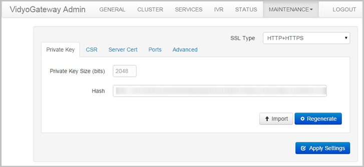
- Click Import. The Import Private Key pop-up displays.
- Click Choose File to locate the private key file.
- Enter a password in the Password field to encrypt data.
- Click Import. A Confirmation pop-up displays.
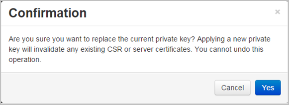
- Click Yes. If the upload completes, a system notification displays indicating the private key installed successfully.
Regenerate an SSL private key
This system uses an asymmetrical (private key and public key) cryptosystem for security. Choose the key size you desire and click the Regenerate button to create your private key.
|
Note To regenerate an SSL Private Key, you must first disable HTTPS. Changes made to an SSL Private Key require a CSR and SSL Server Certificate. This includes importing existing keys, exporting existing keys, and regenerating new keys. |
To regenerate an SSL Private Key:
- Log in to the Admin portal using your System Console account. The General > VidyoPortal page displays by default.
- Navigate to MAINTENANCE > SECURITY. The Maintenance > Security > Private Key page displays by default.
- Click Regenerate. The Regenerate Private Key pop-up displays.
- Select 1024, 2048, or 4096 as your Private Key Size.
Note
Some countries or CAs limit the key size. Observe the limitations in effect in your country. Check with your CA for Key Size requirements.
- Click Regenerate. If the change completes, a system notification is shown indicating the private key was regenerated successfully.
Generate and view an SSL CSR
A Certificate Signing Request (CSR) is a message sent to a certification authority (CA) to request a public key certificate for a person or web server. Most public key certificates issued are SSL certificates, which are used to secure communications with web sites. The CA examines the CSR, which it considers to be a wish list from the requesting entity. If the request is in line with the CA's policy or it can be modified to bring it in line, the CA issues a certificate for the requesting entity.
Generate an SSL CSR
To generate an SSL CSR:
- Log in to the Admin portal using your System Console account. The General > VidyoPortal page displays by default.
- Navigate to MAINTENANCE > SECURITY. The Maintenance > Security > Private Key page displays by default.
- Click the CSR subtab.

- Check with your CA and carefully enter correct values for the following:
- Country Code (the 2 character ISO 3166 country code)
- State or Province Name
- Locality/City
- Organization
- Organization Unit
- Common Name (the FQDN of the server)
- Email Address
- Provide all field information exactly as you registered it with your domain registration provider. You should consider all information on this screen mandatory before you click Generate/Regenerate.
Note
Click Cancel to reload any previously saved field information.
Your SSL CSR is generated based on the SSL Private Key you entered during Import an SSL private key or Regenerate an SSL private key.
View an SSL CSR
To view an SSL CSR:
- Log in to the Admin portal using your System Console account. The General > VidyoPortal page displays by default.
- Naviagate to MAINTENANCE > SECURITY. The Maintenance > Security > Private Key page displays by default.
- Click the CSR subtab.
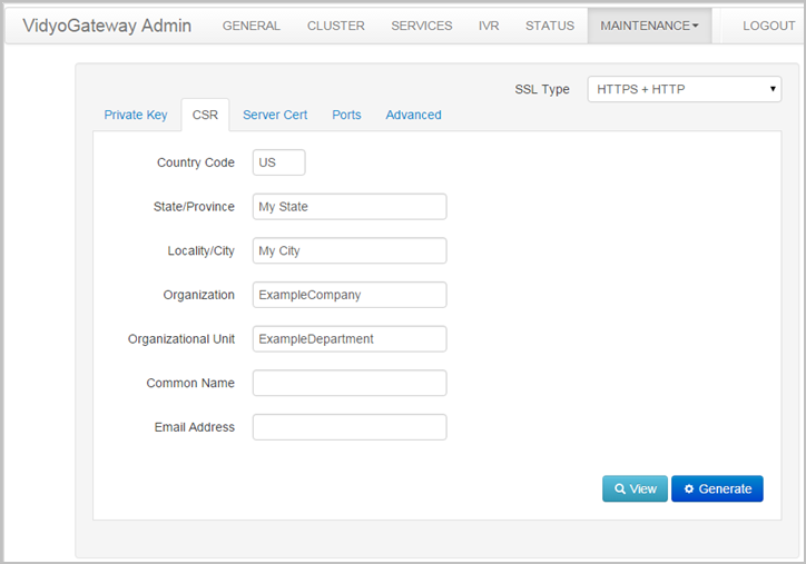
- Click View. The Certificate Signing Request pop-up displays.
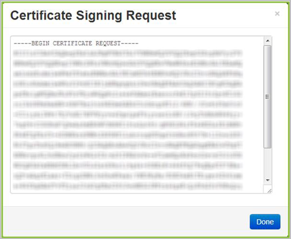
- Click Done.
About certificates received from your certificate authority
Most CAs instantly send certificates and returns at least a domain (server) certificate and may return a root and one or more intermediate certificates in separate files. However, some authorities may provide the certificate data in a single email. You must copy the certificate data from the email into separate, respective files.
|
Note When selecting the certificate type from your CA, be sure to select Apache2 or Tomcat. If neither, the format supported by VidyoGateway is base64 X.509 pem or PKCS#7 (.p7b). |
Your certificate authority may provide three types of files:
- The domain certificate file. This is often named or titled server certificate.
- One or more intermediate certificate files. This is optional.
- The root certificate file.
Again, the certificate authority may send you these files, or require you to download them from their website. Often, the certificates are not clearly identified, requiring you to identify each file type.
As mentioned, if your certificate authority provides certificate files in an email message, you must copy and paste the appropriate text for each certificate type into a separate file and save it with the correct extension, as described in the next section. Be sure to use a text editor that doesn’t append carriage returns at the end of each line.
We recommend the following guidelines to identify certificate files from your CA:
- The domain file normally contains your server’s common name or FQDN.
- Intermediate files often contain the character string “inter” somewhere in the file name. Once you identify which ones are the intermediates, you can then identify the root certificate file by process of elimination.
- The remaining file is the CA’s root certificate file.
The CA may also only return the domain (server) certificate, and if needed or required, the root and/or intermediate certificates need to be located, and manually downloaded from the CA’s website.
If the root and/or intermediate certificates were not provided to you, your Vidyo server includes a default bundle of common CA root and intermediate certificates. If you are using a mainstream CA, the root and intermediate certificates may not be needed.
|
Note Some CAs have several root and/or intermediate certificates available depending on the type of certificate you have ordered. Be sure to locate the appropriate matching root and/or intermediate certificates for your domain certificate. Contact your CA for assistance if you’re not sure. |
CAs provide different kinds of certificate file(s) to customers. Regardless, the following certificates should be a part of what your CA provides to you:
- Domain Certificate (may have a .domain, .crt, or .cer extension).
- Intermediate Certificate(s) (optional, may be one or more, and may have an .inter, .crt, or .cer extension).
- A Root Certificate (may have a .root, .crt, or .cer extension).
Certificate files versus bundles
Your CA may instead provide you with a .p7b file, which may contain Root and Intermediate or Root, Intermediate, and Server Certificate content. Check with your CA to find out exactly where each certificate is located. Your Vidyo server accepts the .pem, .crt, .cer, .der, .p7b, and .pfx formats. The .pfx format additionally includes the private key which may be password protected.
- Certificate Files (.pem, .crt, .cer, and .der) are imported using the Server Certificate, Server CA Certificates, and Advanced tabs. For more information, see Upload or edit your server certificate, Append the CA chain bundle, and Import Client Root CA Certificates from the Advanced tab.
- Bundles (.p7b, .pfx, and .vidyo) are imported and/or exported (only .vidyo files can be exported) from the Advanced subtab. For more information, see Import certificates from a certificate bundle, and Export a security bundle containing your certificate configuration.
Upload or edit your server certificate
Perform the steps in this procedure after you receive certificate files back from your certification authority. An unsigned (self-issued) certificate does not provide a guarantee of security to your users.
Your Vidyo server checks certificates for validity based on the certificates issued date range. Therefore, make sure that the time zone of your server is configured correctly prior to applying your certificate. For more information about setting the time zone of your server, see View application and system information.
If you instead plan on using self-signed certificates, you can click Generate Self-Signed to have the server sign its own certificate (self-signed). Clicking Generate Self-Signed and confirming removes your currently implemented server certificate.
Edit your server certificate
Changes made to an SSL Private Key require a CSR and SSL Server Certificate. This includes uploading existing keys, editing existing keys, and regenerating new keys.
To edit a server certificate:
- Log in to the Admin portal using your System Console account. The General > VidyoPortal page displays by default.
- Navigate to MAINTENANCE > SECURITY. The Maintenance > Security > Private Key page displays by default.
- Click the Server Cert subtab.
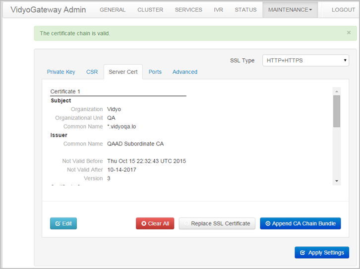
- Click Edit. The Server Certificate pop-up displays.
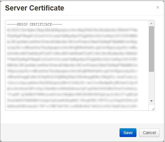
- Modify certificate data in the scrollable text region on the pop-up as desired.
- Click Save. If the edit completes, a system notification displays indicating the change was successful.
Append the CA chain bundle
In addition to issuing SSL Certificates, a Trusted Root CA certificate can also be used to create another certificate, which in turn can be used to issue SSL Certificates. The majority of SSL certificates in use around the world are chained certificates of this type. As the Intermediate Certificate is issued by the Trusted Root CA, any SSL Certificates issued by the Intermediate Certificate inherits the trust of the Trusted Root – effectively creating a certification chain of trust. In many cases the chaining is not limited to a single intermediate. More than one intermediate certificate may be part of a Certificates Bundle.
To append CA chain bundle:
- Log in to the Admin portal using your System Console account. The General > VidyoPortal page displays by default.
- Navigate to MAINTENANCE > SECURITY. The Maintenance > Security > Private Key page displays by default.
- Click the Server Cert subtab.
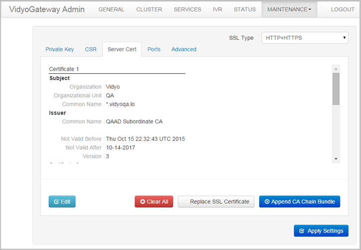
- Click Append CA Chain Bundle. The Append CA Chain Bundle pop-up displays.
- Click Choose File to locate the file.
- Click Upload. A Confirmation pop-up displays.
- Click Yes.
Configure HTTPS port settings for your Admin Pages
The Applications tab is also used for Management Interface settings. For more information, see Configure your Vidyo server’s Management Interface and port.
If you set the HTTPS Port to anything other than 443, users have to manually add the port to their URL requests in their browsers.
To configure the HTTPS Port settings for your VidyoGateway Admin Pages:
- Log in to the Admin portal using your System Console account. The General > VidyoPortal page displays by default.
- Navigate to MAINTENANCE > SECURITY. The Maintenance > Security > Private Key page displays by default.
- Click the Ports subtab.
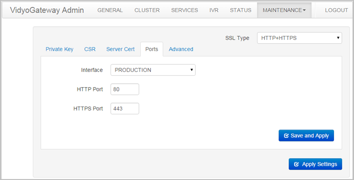
The HTTPS port is set to 443 by default. You can change the port value if necessary. Otherwise, leave it as 443. - Click Save and Apply.
Note
Any active calls going through your specific Vidyo server are dropped when you click Save and Apply.
A Confirmation pop-up displays.
- Click Yes. If the changes are applied to your Vidyo server, a system notification displays indicating the settings saved successfully.
Import Client Root CA Certificates from the Advanced tab
The Advanced subtab is used to upload trusted Client Root CA Certificates. This includes all Intermediate and Root Certificates.
|
Note If your system requires trusting other secure systems such as VidyoPortals, VidyoRouters, and/or an OCSP Responder, their certificates must also be uploaded in this subtab. The Advanced subtab is also used for OCSP. For more information, see Configure OCSP. |
Import a Client CA Certificate
Vidyo servers ship with a default trusted Certificate Authority (CA) bundle that is enabled by default. This Advanced subtab function allows you to enable or disable the use of this list.
You can view the bundle by clicking the View button.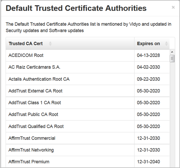
To import a client CA cert:
- Log in to the Admin portal using your System Console account. The General > VidyoPortal page displays by default.
- Navigate to MAINTENANCE > SECURITY. The Maintenance > Security > Private Key page displays by default.
- Click the Advanced subtab.
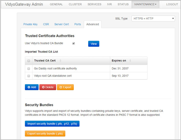
- Click Add in the Trusted Certificate Authorities section. The Add Trusted Certificate Authority pop-up displays.
- Click Choose File to locate the client CA cert.
- Click Upload. A Confirmation pop-up displays.
- Click Yes. If the changes are applied to your Vidyo server, a system notification displays indicating the settings saved successfully.
Import certificates from a certificate bundle
To import a bundle:
- Log in to the Admin portal using your System Console account. The General > VidyoPortal page displays by default.
- Navigate to MAINTENANCE > SECURITY. The Maintenance > Security > Private Key page displays by default.
- Click the Advanced subtab.
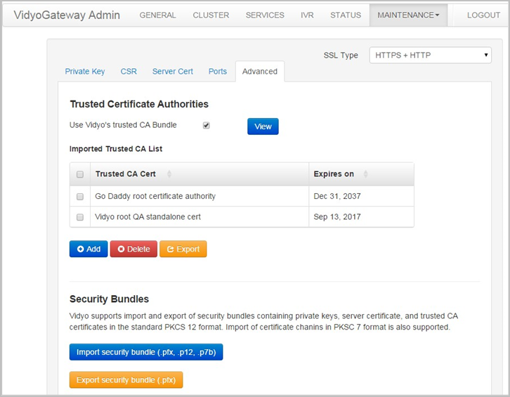
- Click Import security bundle (.pfx, .p12, .p7b) in the Trusted Certificate Authorities section. The Import Security Bundle pop-up displays.
- Click Choose File to locate the bundle.
- Enter the password if using the .pfx format.
- Click Upload. A Confirmation pop-up displays.
- Click Yes. If the changes are applied to your Vidyo server, a system notification displays indicating the settings saved successfully.
Export a security bundle containing your certificate configuration
To export your security configuration:
- Log in to the Admin portal using your System Console account. The General > VidyoPortal page displays by default.
- Navigate to MAINTENANCE > SECURITY. The Maintenance > Security > Private Key page displays by default.
- Click the Advanced subtab.
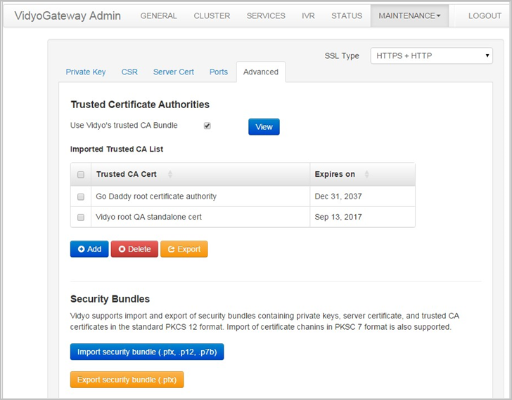
- Click Export security bundle (.pfx) in the Trusted Certificate Authorities section. The Export Security Bundle pop-up displays.
- Enter a password in the Password field.
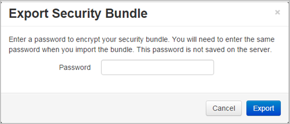
- Click Export. Your browser downloads a password protected file containing your current security configuration.
Enable HTTPS on your Vidyo server
|
Note Do not use the Enable HTTPS button until you’ve completed the steps for securing your Vidyo server. Do not Enable HTTPS Only mode until you are certain HTTPS is working properly. For more information, see VidyoGateway SSL and HTTPS security procedure overview. |
Enable HTTPS and HTTP
To enable HTTPS and HTTP:
- Log in to the Admin portal using your System Console account. The General > VidyoPortal page displays by default.
- Navigate to MAINTENANCE > SECURITY. The Maintenance > Security > Private Key page displays by default.
- Select HTTPS+HTTP from the SSL Type drop-down. A Confirmation pop-up displays.
- Click Yes. If the changes are applied to your Vidyo server, a system notification displays indicating that HTTPS is enabled. You can now browse your Vidyo server over HTTPS.
- Browse to the VidyoGateway Admin Pages to confirm that HTTPS is working properly and that the browser does not post any security errors.
Be sure to include the HTTPS header in the URL (for example, https://[FQDN]). Verify that HTTPS displays on the left side of the address bar and that a lock icon displays (typically in the lower right corner). Some browsers emphasize an HTTPS session with a color like green or blue.Note
You can also verify your signed certificate by displaying information for it in your web browser. See the documentation that came with your web browser for information.
If your browser generates a root certificate error, first check that your operating system has the latest root certificates update applied.
- Continue with the next procedure if you are successful browsing to your Vidyo server using HTTPS and you do not receive any browser errors.
Note
If you are unable to connect to your Vidyo server over HTTPS, see Recover from an HTTPS failure.
Enable HTTPS only
To enable HTTPS Only:
- Log in to the Admin portal using your System Console account. The General > VidyoPortal page displays by default.
- Navigate to MAINTENANCE > SECURITY. The Maintenance > Security > Private Key page displays by default.
- Select HTTPS Only from the SSL Type drop-down. A Confirmation pop-up displays.
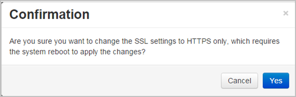
- Click Yes. If the changes are applied to your Vidyo server, a system notification displays indicating that HTTPS Only is now enabled.
Recover from an HTTPS failure
If HTTP is disabled, and you can no longer browse to the Vidyo server using HTTPS, you can disable HTTPS and re-enable HTTP browsing using the System Console menu and selecting Option 16. For more information, see Configure VidyoGateway via the system console.
Configure your Vidyo server’s Management Interface and port
Your Vidyo server allows for the configuration of a secondary Ethernet interface that can be used to access the management capabilities of the system. The secondary Ethernet interface is typically on a segregated network from the main production interface allowing for increased security and firewall protection.
You can move the VidyoGateway Admin Pages to the Management Interface so they are only accessible from that location.
As shown in the following table, the Management Interface is referred to by different names on the physical interface of the server and on the System Console and the VidyoGateway Admin Pages on the Maintenance > Security > Ports subtab:
| Physical interface | System Console and VidyoGateway Admin Page Ports Tab |
| GB1 | PRODUCTION |
| GB2 | MANAGEMENT |
|
Note If the Management Interface is enabled, SNMP is only available on the Management Interface. The Management Interface should not be used to transfer any media. The Management Interface should not be used to transfer any media. |
Enable the Management Interface in the System Console
To enable the Management Interface, see Configure the IPV4 Management Interface.
Move your VidyoGateway Admin Page to the Management Interface
Now you can explicitly move access to your VidyoGateway Admin Pages to the Management Interface.
|
Note Unlike applications which you must explicitly move to the Management Interface, SNMP will be automatically moved to the Management Interface as soon as the Management Interface is enabled on the VidyoPortal. |
To move your VidyoGateway Admin Page to the Management Interface:
- Log in to your VidyoGateway using your system console account. The General > VidyoPortal page displays by default.
- Navigate to MAINTENANCE > SECURITY. The Maintenance > Security > Private Key page displays by default.
- Click the Ports subtab.
- Select MANAGEMENT from the Interface drop-down. Optionally, you can also change the Port to which your VidyoGateway is bound.
- Click Save and Apply.
Note
After clicking Save and Apply, your changes are applied immediately; therefore, if your VidyoGateway Admin Page is moved, you are logged out and it is no longer accessible from the Production Interface (PRODUCTION).
Configure OCSP
You can enable or disable OCSP (Online Certificate Status Protocol) from the VidyoGateway as well as disable it from the System Console.
Enable OCSP from the VidyoGateway
- Log in to the Admin portal using your System Console account. The General > VidyoPortal page displays by default.
- Navigate to MAINTENANCE > SECURITY. The Maintenance > Security > Private Key page displays by default.
- Click the Advanced subtab.
- Click the Configure Client Certificate Authentication button in the Client Certificate Authentication section.
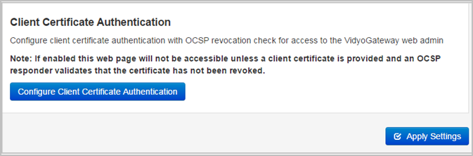
The Client Certificate Authentication pop-up displays.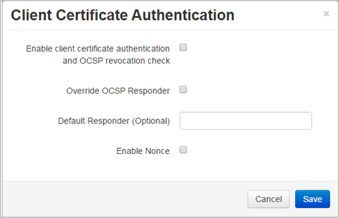
- Select the Enable client certificate authentication and OCSP revocation check.
- Select the Override OCSP Responder checkbox and enter the IP or FQDN address of the new responder in Default Responder (optional) field if you want to override the OCSP responders specified in the Client, Intermediate, and Root certificate.
- Select Enable None if necessary.
- Click Save.
- Click Apply Settings in the Client Certificate Authentication section. The Configure Client Certificate Authentication button changes to the Disable Client Certificate Authentication button.
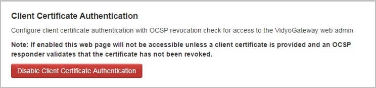
For VidyoGateway, this will immediately require OCSP certificate verification for the VidyoGateway Admin Pages.Note
The server must have access to the OCSP Responders specified in the certificates or the overridden Responder. Also, be sure that the configured DNS server can resolve the FQDNs of all the OCSP Responders.
Disable OCSP from the VidyoGateway
To disable OCSP from the VidyoGateway:
- Log in to the Admin portal using your System Console account. The General > VidyoPortal page displays by default.
- Navigate to MAINTENANCE > SECURITY. The Maintenance > Security > Private Key page displays by default.
- Click the Advanced subtab.
- Click the Disable Client Certificate Authentication button in the Client Certificate Authentication section.
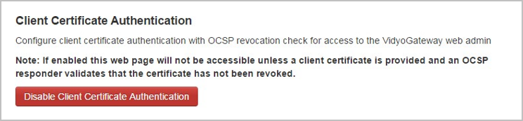
A confirmation message displays at the top of the window stating “Disabled client certification authentication.” The Disable Client Certificate Authentication button changes to the Configure Client Certificate Authentication button.
Disable OCSP from the System Console
If you are locked out of the VidyoGateway Admin Pages, follow the steps below to disable OCSP.
To disable OCSP from the System Console:
- Log in to the Admin portal using your System Console account. The Main Menu displays.
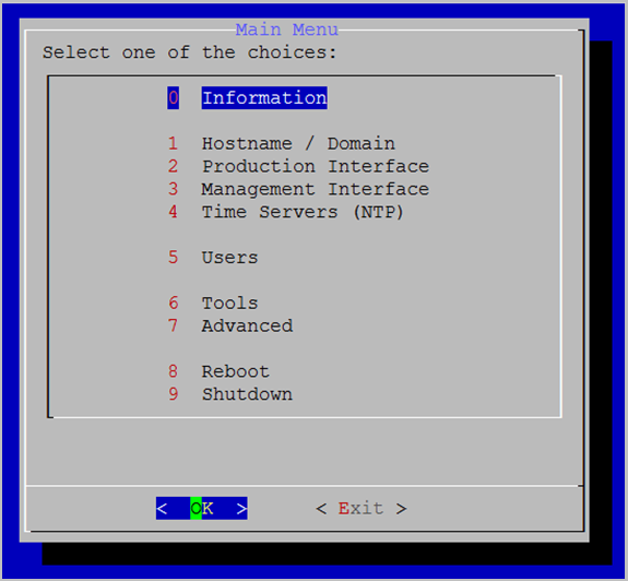
- Enter 7 to select the Advanced option.
- Press the Enter key to select OK. The Main Menu for the Advanced configuration displays.
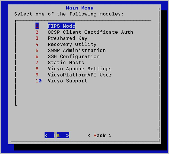
- Enter 2 to select the OCSP Client Certificate Auth option.
- Press the Enter key to select OK. The OCSP Menu displays.
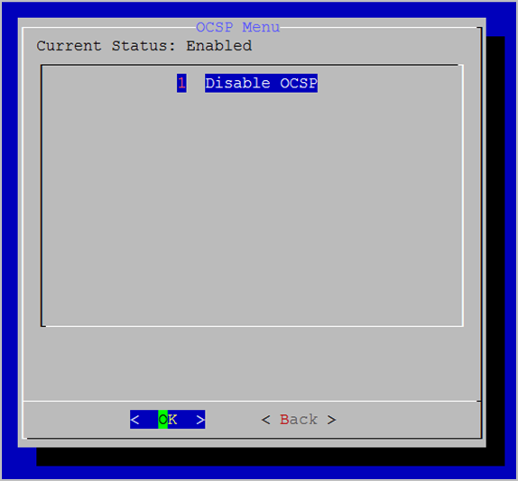
- Enter 1 to select the Disable OCSP option.
- Press the Enter key to select OK. A confirmation prompt displays.
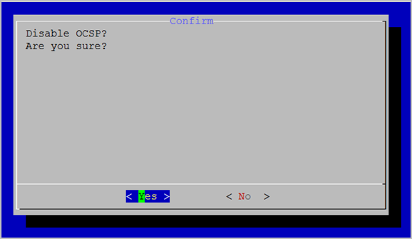
- Press the Enter key to select Yes. A message displays stating “OCSP Disabled.”
- Press the Enter key to select OK. The OCSP Menu displays.
Upgrade your VidyoGateway
When you receive a software update from Vidyo, you can install it using the Upgrade page.
|
Note Once the VidyoGateway is upgraded, a downgrade is not possible. For specific information about upgrading your VidyoGateway, refer to the VidyoGateway Release Notes for your corresponding software release version. For information about upgrading your entire Vidyo conferencing system, refer to the VidyoPortal and VidyoRouter Administrator Guide. |
To upgrade your VidyoGateway:
- Log in to the Admin portal using your System Console account. The General > VidyoPortal page displays by default.
- Navigate to MAINTENANCE > UPGRADE. The current software version is shown in the Software Version field.
- Click Choose File to locate the VidyoGateway installation file.
- Click Upgrade and Reboot. The Upgrade and Reboot pop-up displays to inform you that the change drops all the active conference calls on your VidyoGateway server.
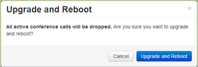
- Click Upgrade and Reboot to confirm. After your VidyoGateway server reboots, return to the Maintenance > Upgrade tab and confirm that the upgraded software version is the one currently being used by your system.
Shut down or reboot your VidyoGateway
You can either shut down or reboot your VidyoGateway server manually using the Shutdown/Reboot page.
Shut Down Your VidyoGateway Server
To shut down your VidyoGateway server:
- Log in to the Admin portal using your System Console account. The General > VidyoPortal page displays by default.
- Navigate to MAINTENANCE > SHUTDOWN / REBOOT.
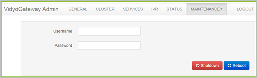
- Enter your username and password.
- Click Shutdown. The Shutdown pop-up displays to inform you that you will need physical access to the server to start your VidyoGateway server up again. Shutting down drops all the active conference calls on your VidyoGateway server as well.
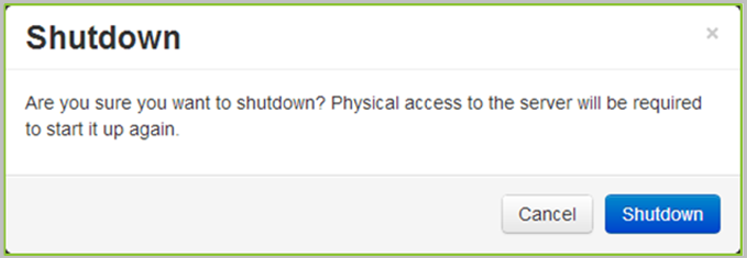
- Click Shutdown to confirm.
Reboot your VidyoGateway server
To reboot your VidyoGateway server:
- Log in to the Admin portal using your System Console account. The General > VidyoPortal page displays by default.
- Navigate to MAINTENANCE > SHUTDOWN / REBOOT.
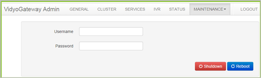
- Enter your username and password.
- Click Reboot. The Reboot pop-up informs you that the reboot drops all the active conference calls on your VidyoGateway server.
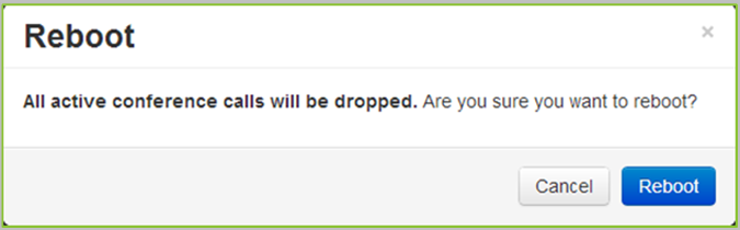
- Click Reboot to confirm.
Extend your VidyoGateway session
After four minutes of inactivity, the Extend session pop-up displays. Click Continue to extend your session for 15 minutes; otherwise, click LOGOUT to log out of your VidyoGateway.
Log out of your VidyoGateway
You can manually log out of your VidyoGateway server using the Logout tab.
To log out of your VidyoGateway server:
- Log in to the Admin portal using your System Console account. The General > VidyoPortal page displays by default.
- Click the LOGOUT tab. You are immediately logged out of your VidyoGateway server.
